I simulated an imaging system consists of objective lens, doublet lens, and a reflective object which is the point non-sequential objects coming in the path. All ray tracing work well for all objects and can be easily observed in the 3D optical layout, but the problem is when I add a detector after the reflective object. Rays doesn't reach the detector and even if I bring the detector closer to the reflective object, nothing would be observed in the detector viewer. While if I use another non-sequential object ray tracing would be fine and they go on their path.
I would be happy if someone that has the same problem or know what is wrong here could answer the question.
Kind regards,
Best answer by David.Nguyen
Hi Amir,
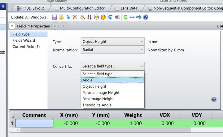
This is a problem that occurs to me frequently. When your field definition is the image height, it means that your system should be able to form an image to measure its height. Otherwise it doesn’t know what the height is and throws an error. This happens when you make relatively drastic changes to your file, and somehow the rays don’t make it to the image plane anymore. To avoid this issue, convert your field definition to something that doesn’t depend on the rays making it to the image plane. In your case, I converted the field to Angle definition.
You can always convert it back to Image Height once you know the rays make it to the image plane.
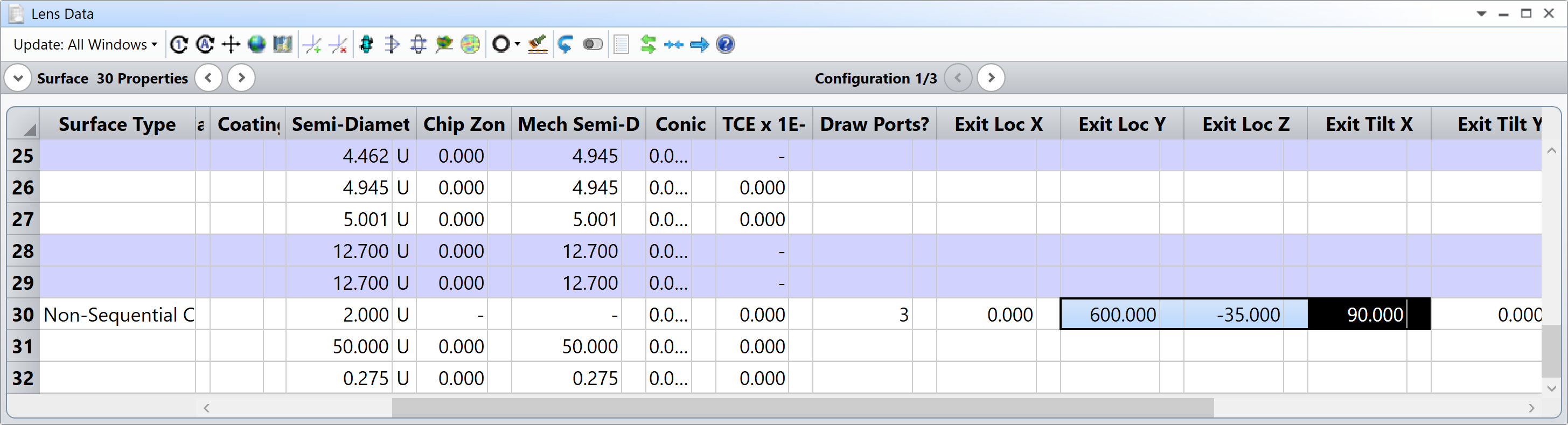
The second problem in your file was the Exit Port Location. To view it, it is easier to have a dummy surface right after your non-sequential component and increase its semi-diameter to a large value (I changed it to 50 mm in your file). Then, simply use the parameters of the Non-Sequential Component surface: Exit Loc X, Y, Z, and Exit Tilt X, Y, Z. I have used rough estimates to position the exit port of your system adequately (you know your system better than me, you should have a better idea of where the exit port should be located). For your reference, here are the values I used:
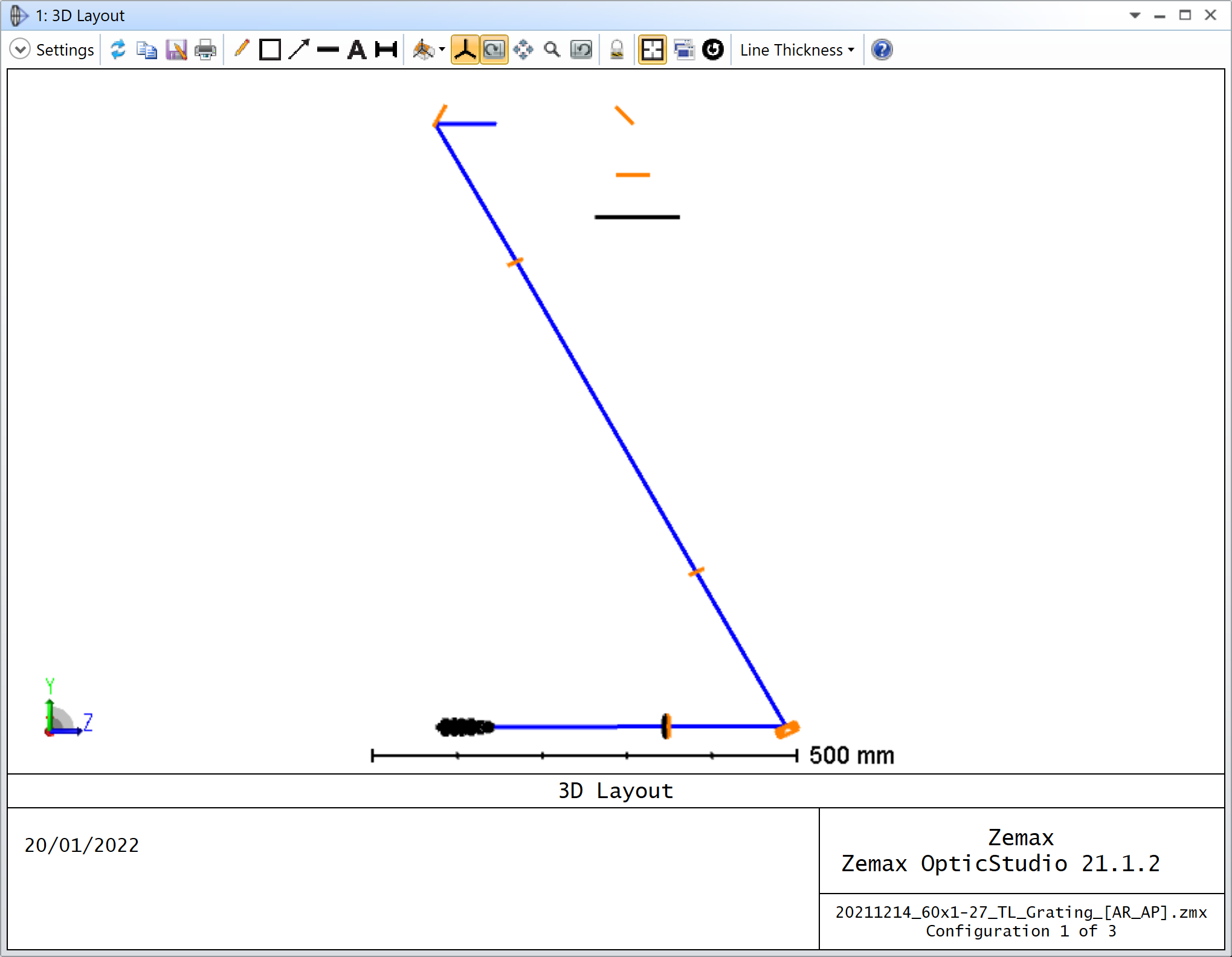
The next problem in your file is that the chief ray doesn’t make it to the Exit Port, and most analysis cannot be calculated.
As you can see in my screenshot above, after the first “BACKGROUND” mirror, the chief ray is terminated, i.e. it doesn’t reach the second “BACKGROUND” mirror, and doesn’t exit the non-sequential component.
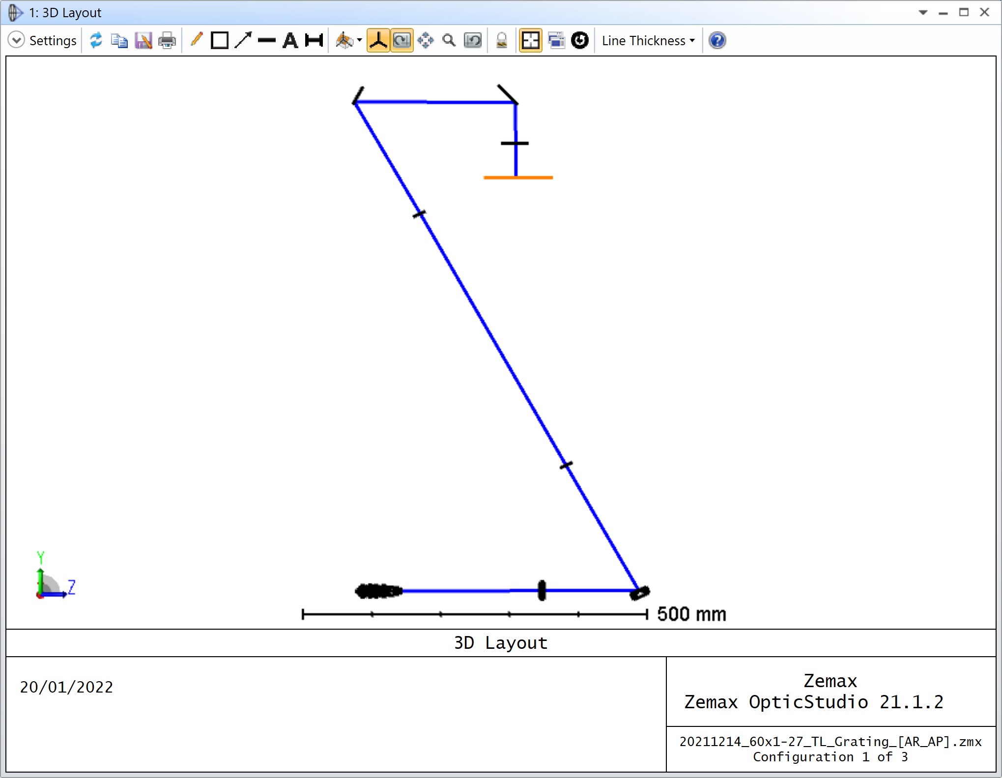
If I increase the Maximum Aperture of this second mirror to 20 mm, the chief ray can reach the image surface.
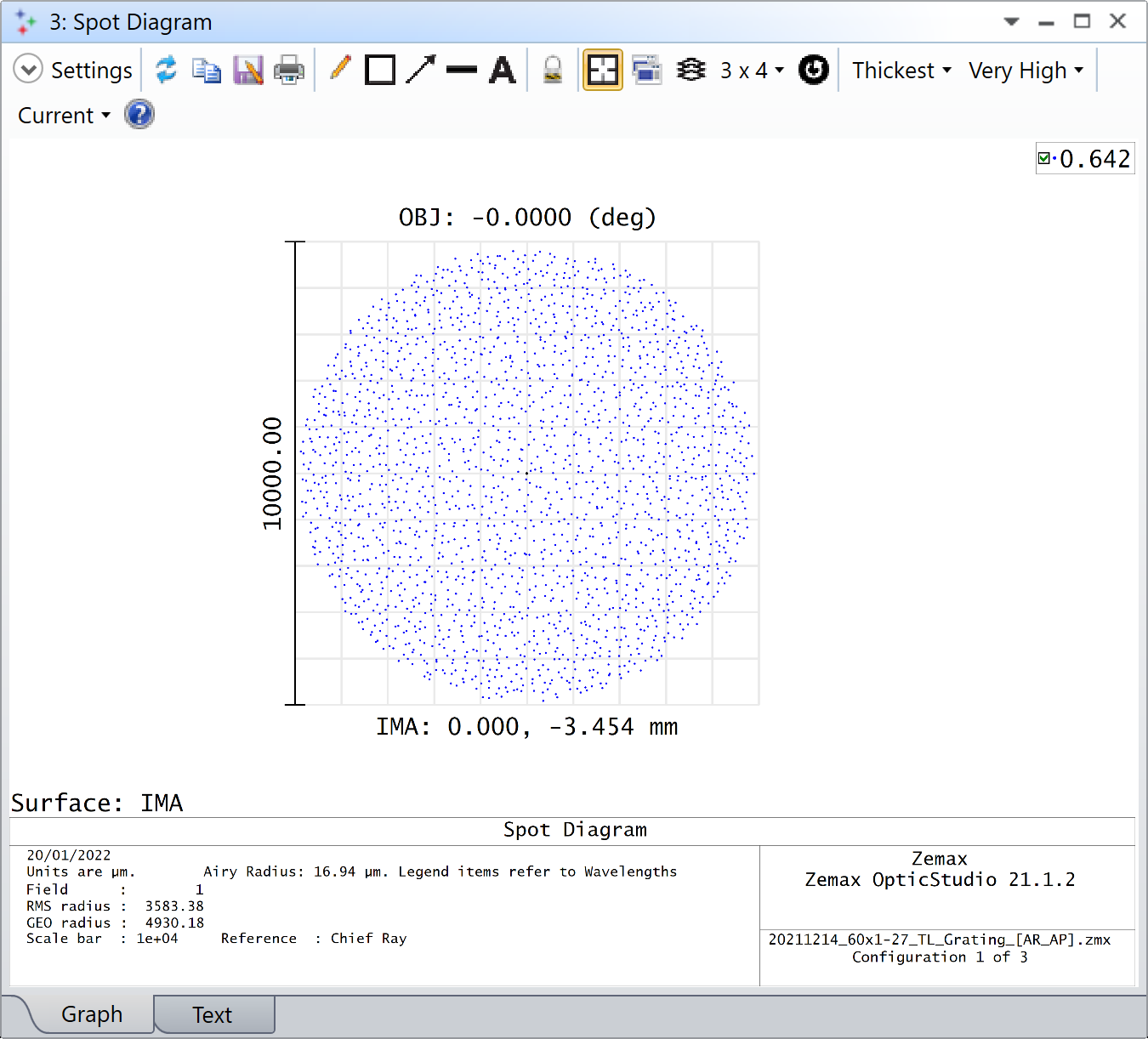
And if you do all that, you can actually use the sequential analysis features such as the spot diagram:
I will be attaching my modified file to this reply for your reference as well.
Not sure I can help, but would you be able to share your file for further investigation? Ideally by pressing File..Create Archive.. and uploading a *.zip of this archive on this thread.
From what I can see, there are no sources in your Non-Sequential Component editor. Therefore, it makes sense that the Detector doesn’t detect anything. To the best of my knowledge, in mixed mode, non-sequential detectors don’t detect sequential rays.
I guess you could let the rays exit your non-sequential component, and use a sequential analysis feature such as Geometric Image Analysis to replace the non-sequential detectors. In order to do so, you may want to adjust your Exit Port location, which is currently just 1 mm away from the doublet (Exit Loc Z in Surface 30 is 1.0).
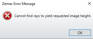
Actually, when I try to change the Exit Port location, an error happens (Picture Below).
I need those sequential rays but couldn’t get the spot diagram on the location I placed the detector. Do you think it’s possible to have image plane there to get the spot diagram? or place the Exit port location after those two non-sequential lenses to get sequential analysis?
This is a problem that occurs to me frequently. When your field definition is the image height, it means that your system should be able to form an image to measure its height. Otherwise it doesn’t know what the height is and throws an error. This happens when you make relatively drastic changes to your file, and somehow the rays don’t make it to the image plane anymore. To avoid this issue, convert your field definition to something that doesn’t depend on the rays making it to the image plane. In your case, I converted the field to Angle definition.
You can always convert it back to Image Height once you know the rays make it to the image plane.
The second problem in your file was the Exit Port Location. To view it, it is easier to have a dummy surface right after your non-sequential component and increase its semi-diameter to a large value (I changed it to 50 mm in your file). Then, simply use the parameters of the Non-Sequential Component surface: Exit Loc X, Y, Z, and Exit Tilt X, Y, Z. I have used rough estimates to position the exit port of your system adequately (you know your system better than me, you should have a better idea of where the exit port should be located). For your reference, here are the values I used:
The next problem in your file is that the chief ray doesn’t make it to the Exit Port, and most analysis cannot be calculated.
As you can see in my screenshot above, after the first “BACKGROUND” mirror, the chief ray is terminated, i.e. it doesn’t reach the second “BACKGROUND” mirror, and doesn’t exit the non-sequential component.
If I increase the Maximum Aperture of this second mirror to 20 mm, the chief ray can reach the image surface.
And if you do all that, you can actually use the sequential analysis features such as the spot diagram:
I will be attaching my modified file to this reply for your reference as well.