How do you define S polarization, P polarization, TE polarization0, TM polarization, X polarization, Y polarization?
Definition of S polarization, P polarization, TE polarization0, TM polarization, X polarization, Y polarization
Best answer by yuan.chen
Polarization is defined as the direction of "oscillation", not the direction in which the electric field travels.
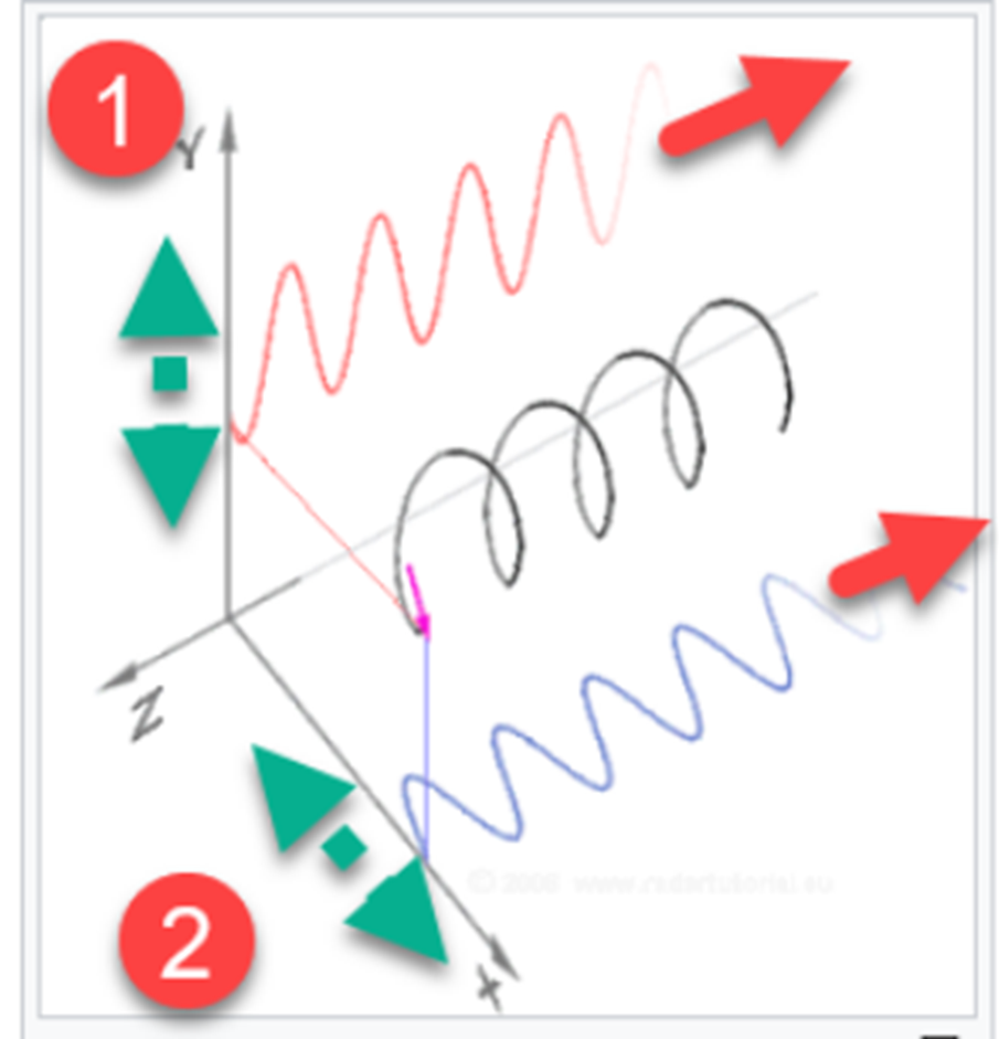
From the figure below, (1) goes in the Z direction, but the electric field oscillates in the Y direction, thus becoming Y-polarized light (linearly polarized light in the Y direction).
(2) It advances in the Z direction, but because the electric field oscillates in the X direction, it becomes X-polarized light (linearly polarized light in the X direction).

A more general definition is defined from the direction of the "plane of incidence".
The plane formed by the incident light vector and the boundary normal vector is called the incident plane. When the electric field oscillates perpendicular to the incident surface, it is defined as s-polarized light or TE-polarized light. When the electric field oscillates parallel to the plane of incidence, it is defined as p-polarized light or TM polarized light. S is a vertical word in German with the acronym Senkrecht. p stands for parallel.
More information about S and P polarization states: How does OpticStudio define the s- and p-polarization states? | Zemax Community
In Zemax, the local coordinates used to define the polarization state of the light source are Jx (the energy corresponding to the S component) and Jy (the energy that defines the P component).
If you want to polarize light in a specific direction, you can model it by setting the polarization state of the light source + reference axis + rotation of the light source.
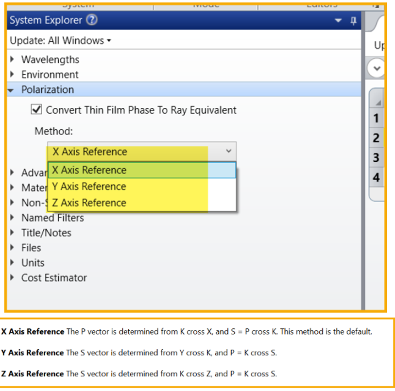
The reference axis is shown in the figure below.

If you want to set it to X-direction polarization as a prerequisite for light propagation in the Z direction, you need to choose a Y-axis reference.
In this case, S=Y crosses K, so S is in the X direction.
Thus, (Jx,Jy)=(1,0) & Y axis reference causes light to propagate in the Z direction and polarize in the X direction.
Similarly, if the light source is polarized in the Y direction, you can choose an X-axis reference so that there is no component in the Ex direction.
When linearly polarized in a specific direction, the light source can be rotated by an angle, thus changing the polarization direction of the resulting light.
Enter your E-mail address. We'll send you an e-mail with instructions to reset your password.


