I am wondering if there is a way to define a custom source based on its field intensity (Ex,Ey) and phase in nonsequential mode similar to the zemax beam file format. The aim of my simulation is to import an near field profile from the FDTD simulation into zemax sp I can analyze the propagation of the field profile in NSC system (scattering medium using Monte Carlo simulation) . Any guidance is appreciated.
Best answer by Ali H
Hi Fred,
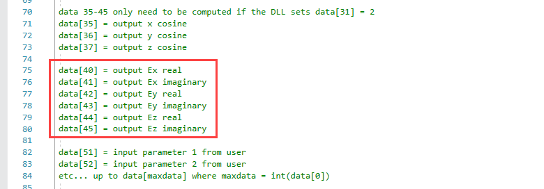
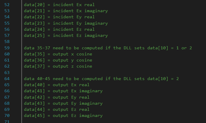
One way I can think of to achieve a source based upon its electric field is to use a diffraction DLL where you can define your electric field and phase directly. Below is an extract from one of the diffractive DLL sample files that comes with OpticStudio:
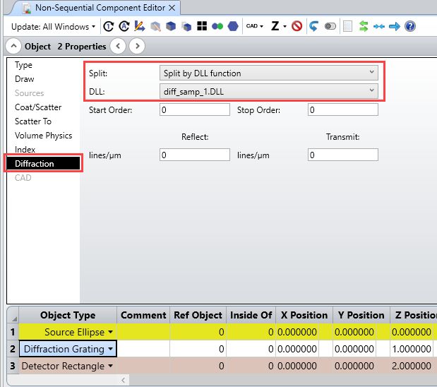
You would need to place a source in front of the Diffraction Grating Object, and then chose Split by DLL function:
One way I can think of to achieve a source based upon its electric field is to use a diffraction DLL where you can define your electric field and phase directly. Below is an extract from one of the diffractive DLL sample files that comes with OpticStudio:
You would need to place a source in front of the Diffraction Grating Object, and then chose Split by DLL function:
Yes, I have looked through the link before but it doesn't allow me to import a zbf file in non-sequential mode (or at least I could not find a way to do so)
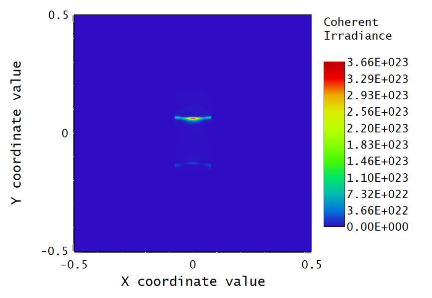
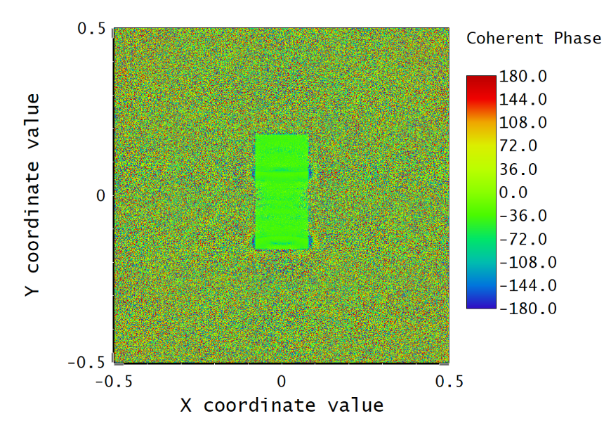
I have attempted the method you have suggested. It was able to define the beam profile correctly, but I don't know if the phase of the source is defined correctly. How come the beam has a coherent phase of 0 for all points at the source as shown below?
I have also noticed that data[32:34] are used to define the derivative of the phase and output phase. I am not sure how these come into play with the electric field.
I am trying to propagate this beam by defining each point in the profile as a spherical point source and observing how the evolution of beam profile in free space. I'm hoping this could serve as an approximation to the Fresnel diffraction but the end results do not seem to perform as expected. Do you see any solution to this?
How are you setting the phase in the .DLL? I'm guessing that the coherent phase profile you're seeing on the detector is likely due to how you're setting data[32:34]. The electric field values will have a direct impact here, so I'd recommend that you do a little reading up on complex electric field notation. Here are a couple publicly-available resources that I've read through in the past:
If you're reading the electric field values from your .ZBF file, you can take these and determine the phase added at each point on the diffraction surface.
In terms of your goal to observe how the beam profile evolves in free-space, this is challenging to do in Non-Sequential Mode. However, it's quite straightforward to do this using Physical Optics Propagation in Sequential Mode. Is there a specific reason you need to use Non-Sequential Mode in this case?
Thanks for the reference, I will take a look. Currently, I am setting all the imaginary and real components of the electric field based on the method provided by Ali. I set the output phase data[32] as zero. This is why I am confused about the parameter for data[32]. Is there a way to set the phase of the field based on the real and imaginary components. Does zemax track the phase change for all three fields (Ex,Ey,Ez) as it propagates?
The reason why I am trying to work on this in non-sequential mode is that my ultimate goal is to examine how the field evolves in a scattering medium. Hope this clarifies my intention. I have attempted POP in a mixed-mode but I don't know why I don't see the field at the imaging plane. If you think this should work, I can give it another try.
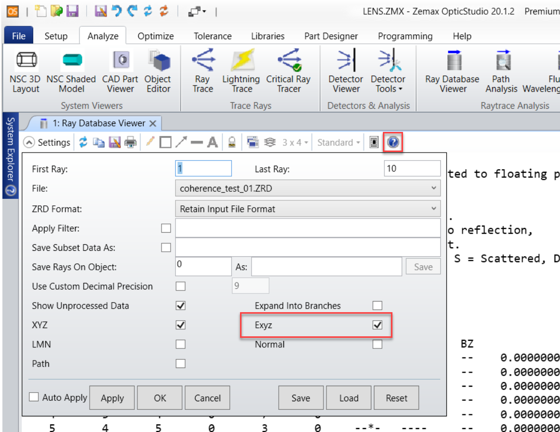
My pleasure. If you're setting data[32] equal to zero, then that likely explains the problem. If you take a look at the sample code I've attached (also available in \Documents\Zemax\DLL\Diffractive), you'll see that data[32] = P, and this pulls information from other data values already defined. What you can do here is use the electric field components as input values to determine a non-zero phase value at different points across the surface. To answer your question about tracking the (Ex,Ey,Ez) values, yes, OpticStudio does store this information about the rays as they intersect objects in the system. Take a look at the Ray Database Viewer, as well as it's Help File to see what exactly is stored.
That said, with respect to your ultimate goal, that makes sense. Thanks for the clarification. I think that this will be doable in Non-Sequential Mode, but it'll certainly be tricky. I'm not sure if you've looked into modeling the scattering medium yet, but you'll likely need to define a custom bulk scatter .DLL to do this. Additionally, you'll need to carefully define it so that you don't lose your phase information as the rays propagate/scatter. Admittedly, I'm not an expert in how to write these, but I'd recommend that you check out these two resources to get you started.
Thanks for the help again. I will try to implement the code with the resources provided. Just a last couple of questions. Why did you say that a custom bulk scatter DLL is required? Any particular functions I need to add to the code? I was thinking of using the Henyey-Greenstein-bulk as a starting point. I have also downloaded the polarization-sensitive scattering from one of the resources provided.
My second question is there a way to record each electric field component(Ex,Ey,Ez) at a certain surface. I have tried to use the ray database viewer but it doesn't allow me to store 1e9 rays.
Lastly, it seems like Zemax doesn't really support the propagation of Ez field as the ray database viewer always shows that field as zero. Not sure if this is related to how polarization is set up in zemax.
I think Nick has suggested using the bulk scattering DLLs because there are two steps you will need to take to achieve the goal of modelling your source through scattering mediums. In step 1, you will use the diffraction DLL as a 'mask' that will define the rays as they are launched from the source. Then, as the rays propagte through your system and scatter, you will have to incorporate a DLL to include polarization-sensitive scattering. In other words, you will make at least two different DLLs to properly model the system.
For this purpose, the Henyey-Greenstein model will work as a starting point. Just make sure to add in the polarization definitions:
Regarding your second question, you could use the NSRA optimization operand to read Ex, Ey, and Ez data segment-by-segment. A segment is created in a scattering event, or when the ray strikes a surface. The details about this operand can be found in the Help System file 'The Optimize Tab (sequential ui mode) > Automatic Optimization Group > Merit Function Editor (automatic optimization group) > Optimization Operands (Alphabetically)'. Alternatively, you can write a script to parse through your full ZRD file. We have a great example of how to do this through the API in the Zemax DATA folder: Zemax\ZOS-API Sample Code. Choose your programming language of choice, and take a look at sample #5 - 'Parsing a ZRD File'.
Finally, OpticStudio will report Ez data. You can confirm that by taking a look at the data of any of our Non-Sequential sample files within Zemax\Samples\Non-sequential. It could be that the DLL you are using has suppressed the Ez component. Have you looked within your DLL to make sure Ez isn't set to be zero?
Let us know if you have any other questions about this. And have a great week!
Just following up, did you happen to get any success with this? I'm also trying to translate Lumerical near-field EM data into Zemax, exploring the diffraction DLL route but not sure how data[32:34] and data[35:37] should be defined from the near-field data.