Solved

Defining a 3D object without CAD import

  • 7 February 2024
  • 3 replies
  • 78 views

Hello,


I am relatively new in Zemax have an issue with defining  or creating new 3D objects in Zemax. I have read the relevant articles in Zemax Knowledge base, however, can’t find a plausible explanation to my question.


What I actually need is to define a UDO (User defined object) by supplying a set of x  y and z coordinates (or a parametric equation with boundaries) in order to perform a stray light analysis in non-sequential mode.


The reason why I want to define it inside of Zemax instead of importing a CAD file is that I want to use Merit function to optimize the dimensions of this predefined object. The object supposed to be a light guide and should reflect off the maximum possible rays of its surface with a total internal reflection so that I can detect them by using a detector polar.  In the case of imported CAD objects, the Merit function cannot optimize its dimensions as far as I can experience.

icon

Best answer by David.Nguyen 13 February 2024, 09:00

View original

3 replies

Userlevel 7
Badge +2

 @Atalha,


There used to be a way for Premium users with SOLIDWORKS, but unfortunately it is now deprecated (and it was super slow):

https://support.zemax.com/hc/en-us/articles/1500005487461-Using-the-OpticStudio-Dynamic-CAD-link-with-assemblies

If you use the built-in Part Designer tool to make your CAD then it is still possible to expose some of its dimensions (but that means remaking your CAD basically, if the geometry even allows...):

https://support.zemax.com/hc/en-us/articles/1500005577282-Designing-a-flood-light-with-OpticStudio-s-Part-Designer

If you want to make your own user-defined Object, this is definitely a possibility, and you will need different resources.

This article explains how to compile the user-defined Object DLL:

https://support.zemax.com/hc/en-us/articles/1500005577602-How-to-compile-a-User-Defined-DLL

(note that you don’t need a header file for user-defined Object)

As far as how to program the DLL, I suggest starting with the HalfCylinder.c example in your {Documents}\Zemax\DLL\Objects. The comments describe how to fill the different cases. I have made another relatively basic example with an ellipsoid object that you can also have a look if you like:

https://github.com/Omnistic/ellipsoid_object

One thing to say is that, all the methods above are substantially slower than using OpticStudio native objects and there’s definitely a learning curve for the user-defined Object. Bottom line is, I strongly suggest to also spend a bit of time thinking whether you could get away with native Objects.
https://support.zemax.com/hc/en-us/articles/1500005487401-Improving-non-sequential-ray-tracing-speeds-with-nested-and-Boolean-objects

I hope this helps and good luck in your endeavor,


David

Hallo David,

thank you so much for your help! 

Since I am using Optic Studio Pro version, I cannot use some of the methods you have proposed (The dynamic link option with Creo Parametric and Autodesk Inventor and also .zpo files via Part Designer, for example)

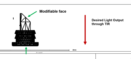
In the case I want to use the last option you have suggested, which could also be adequate for what I want, I created the same part with simple Zemax objects and combined them together to reach the identical light guide part in CAD file.  


As can be seen from the picture, the light rays reach the surface from the left (onto the flat surface of the light guide) and then make a total internal reflection before leaving the light guide from its bottom.

I can change the surface shape of the diagonal face of the light guide by implementing an aspheric or curved shape to maximize the total internal reflection (TIR). The aim is to obtain a homogeneous and equal lighting on the Detector polar, which is located at the bottom with a radial size of 5000 mm.


The origin of my question is, Which operands should I use in the Merit Function editor in order to find out the best possible surface shape ?

Is it also possible to optimize the bottom surface via Merit Function editor? My idea is to introduce some roughness to that surface to increase the scattering off the surface.


I would be grateful if you could kindly help me on that. As a summary: I need to find the best native object type in Zemax (freeform Z, or sag..etc) which can replace the current diagonal face, then find the correct operand in the Merit function editor.

I have attached the .zos file of my project as it might be helpful to explain my question in a more comprehensive way.


Thanks in advance and regards,


Ahmet

Userlevel 7
Badge +2

@Atalha,


Good that you managed with native objects. I don’t have a lot of experience designing such surfaces. I’m not so experienced with designing such objects, but what I can say is that unless the shape of your surface is very specific, a lot of those freeform objects/surfaces can lead to the same shape but they will differ in the way they are optimized. Also, if you have some prior knowledge about how this object will get manufactured, it can be helpful to start with a specific model of the sag. Another thing, if you are going to run this optimization in non-sequential mode, it might be computationally intensive and you want to ensure that as many rays reach your detector as possible. There are some criterion in the Optimization Wizard which you can use, such as Spatial Uniformity. Spatial Uniformity will minimize the standard deviation of all pixels using a NSDD operand. Note that if light doesn’t cover your entire detector, it might causes problems as the change in intensity between the light and dark regions are features of high standard deviation. In such case, you might want to use a different metric for the optimization (and then figure out the corresponding operands to use), or in complex cases use the Bitmap Optimization as described in this article:

https://support.zemax.com/hc/en-us/articles/1500005575582-Using-the-OpticStudio-Non-Sequential-Optimization-Wizards

Alternatively, there are cases where it is possible to make such an optimization in sequential mode, which is substantially more efficient. Have a look at this beam shaper example:

https://support.zemax.com/hc/en-us/articles/1500005489161-How-to-design-a-Gaussian-to-Top-Hat-beam-shaper

Lastly, there are a number of resources regarding freeform optics in the Knowledge base, I suggest browsing a few:

https://support.zemax.com/hc/en-us/search?utf8=%E2%9C%93&query=freeform

At this point this is really a design problem that you’ll have to figure out based on your needs and the constraints of the problem.

Keep us updated of your progress and let me know if anything wasn’t clear.

Take care,


David

Reply