Question

Coordinate Transformations in Non-Sequential


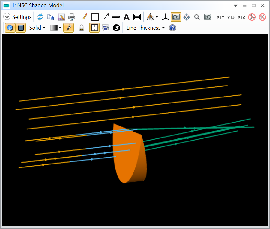
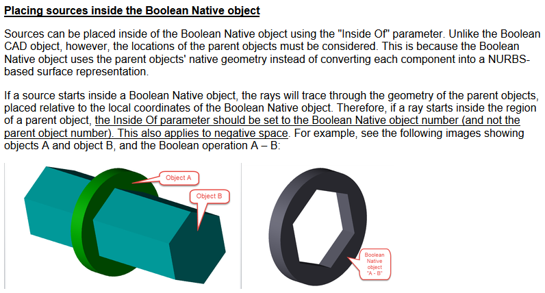
I’m trying to create an orange from boolean orange slices in Zemax.  The question is how to wrangle them into position in the simplest way possible.  I’ve attached a screenshot which shows the LDE and the incorrect placement of the 2nd wedge.  Thanks!

21 replies

Userlevel 7
Badge +2

@Donna.Waters,


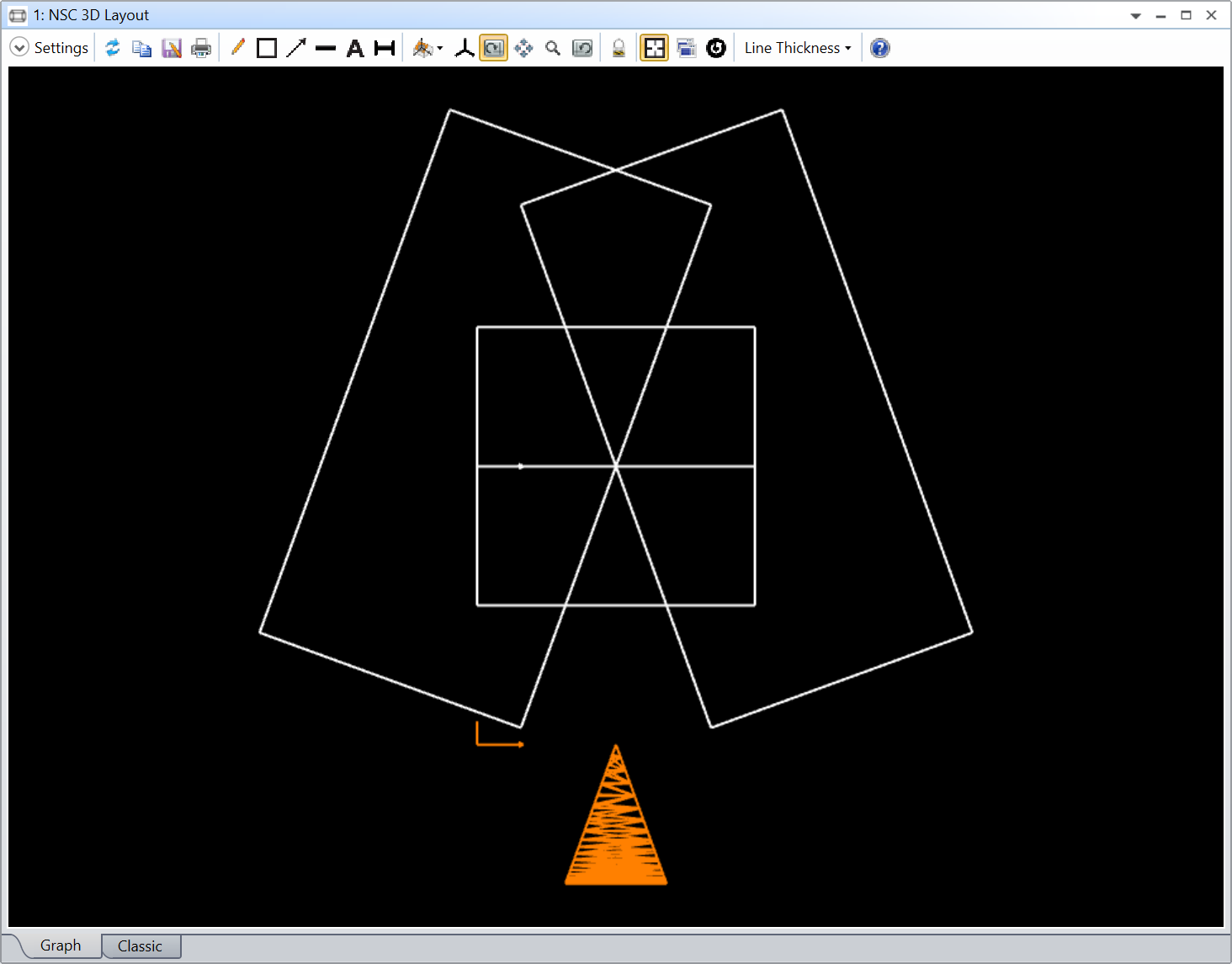
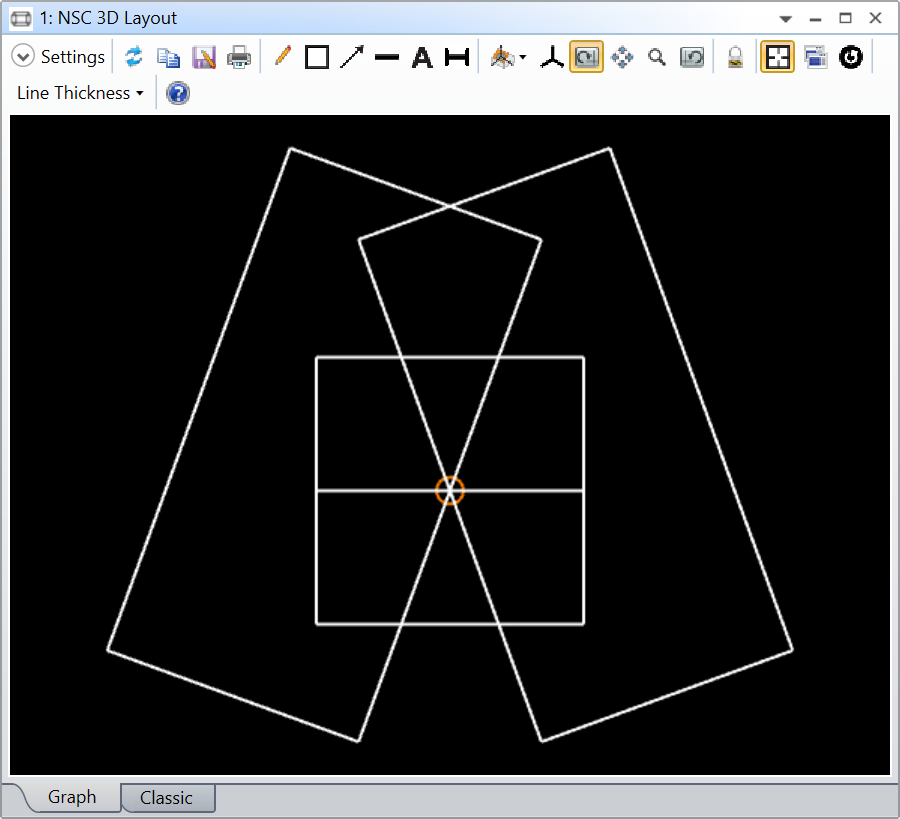
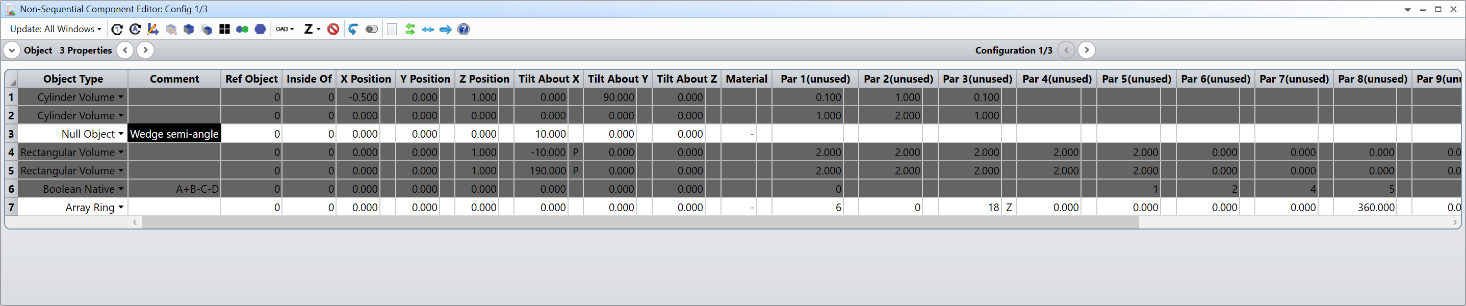
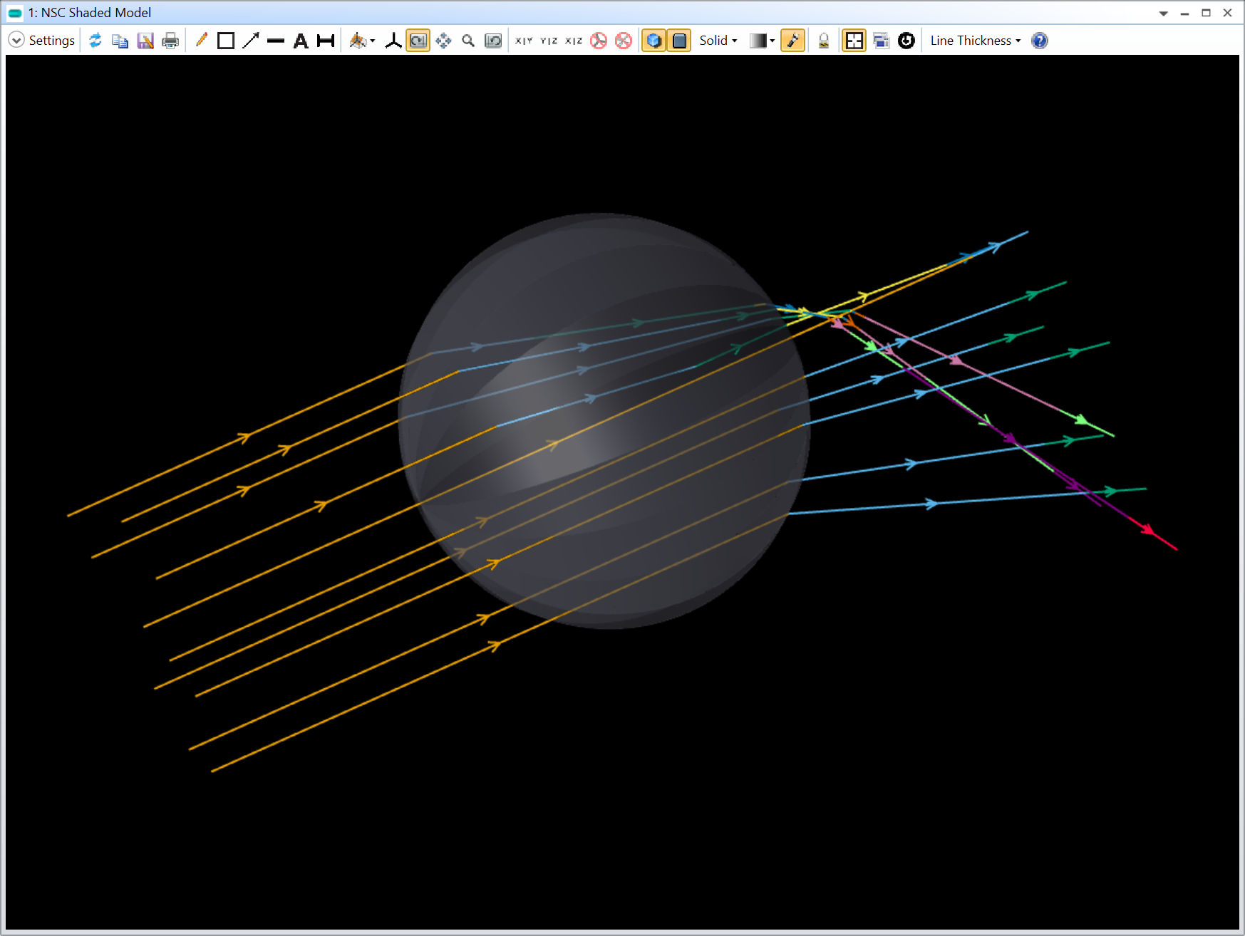
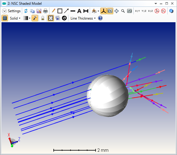
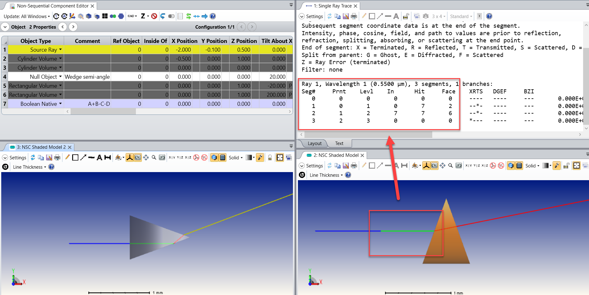
I think you want to leverage the Array Ring object for this problem. However, for the Array Ring to work, you need the local Z axis of the orange wedge to be along the straight line of the wedge. When you cut the Cylinder as you did, the local Z axis is the one from the Cylinder (as shown below, if you double-click on an object it opens its properties and under Draw..Draw Local Axis you can display its local axis).

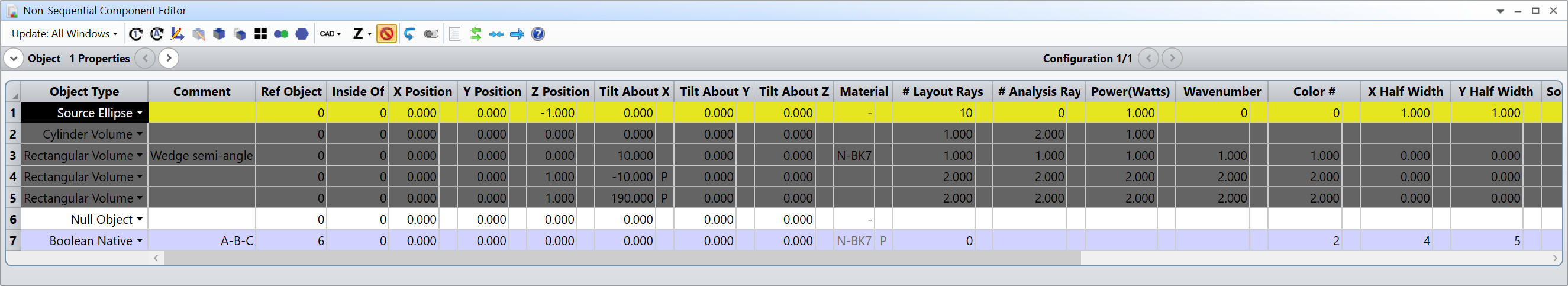
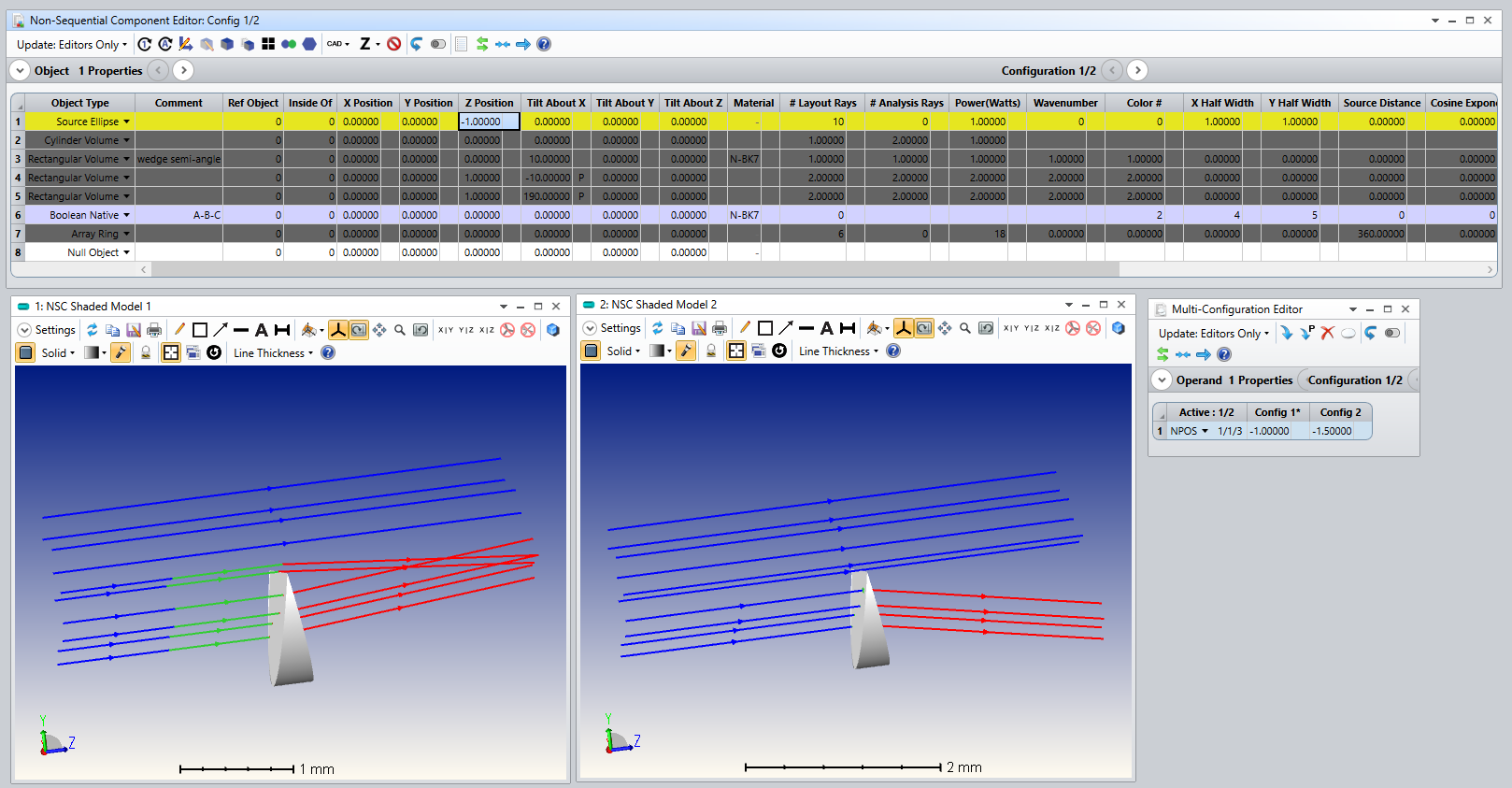
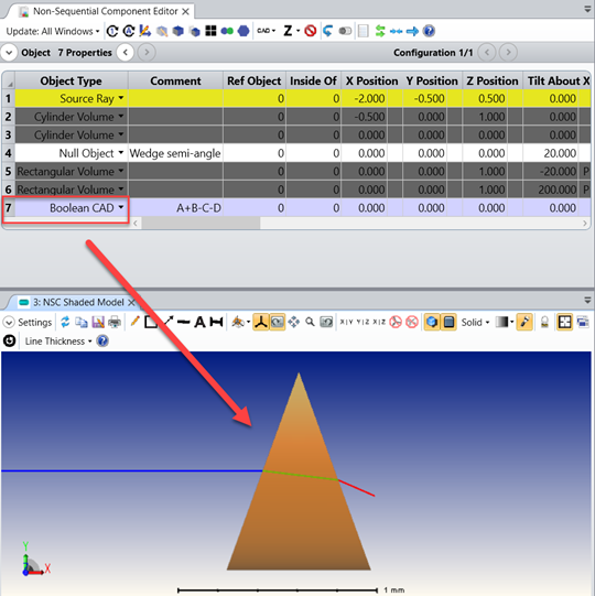
However, we can trick the Boolean native with a dummy Cylinder Volume as such:

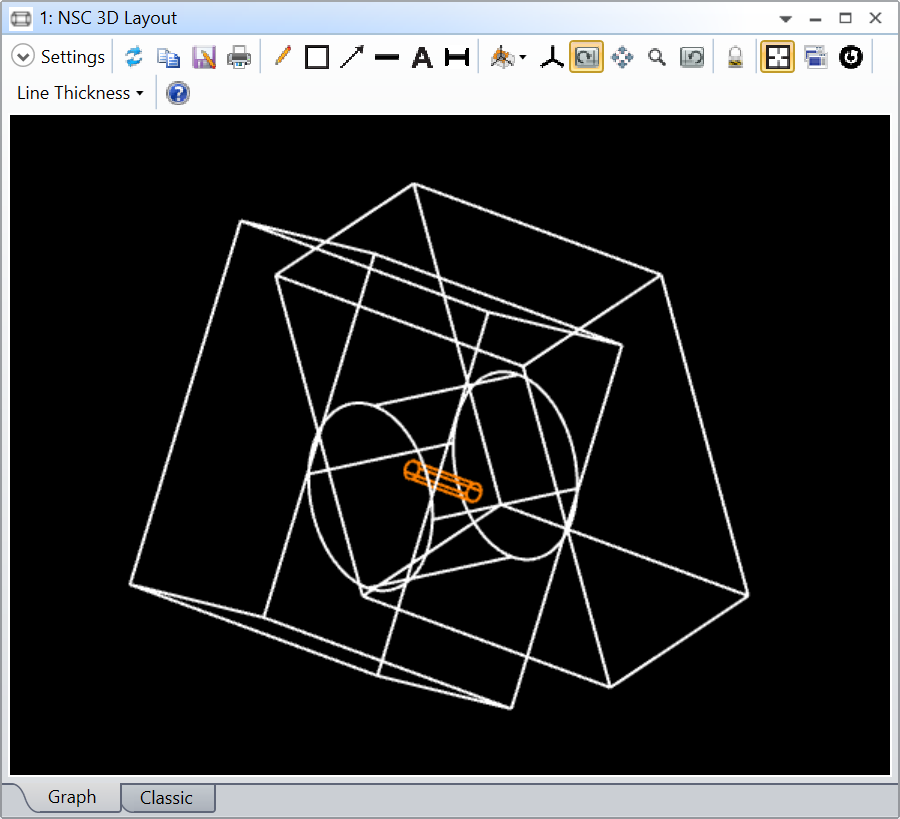
Basically, I have intentionally put a dummy Cylinder Volume inside your main Cylinder Volume with the Local Z Axis of the dummy Cylinder Volume along the straight line of the wedge. The Boolean native is then Cylinder Volume + dummy Cylinder Volume - the two Rectangular Volumes. Because the dummy Cylinder Volume is Object A, the Boolean Native has its Local Z Axis aligned with the straight line of the wedge:

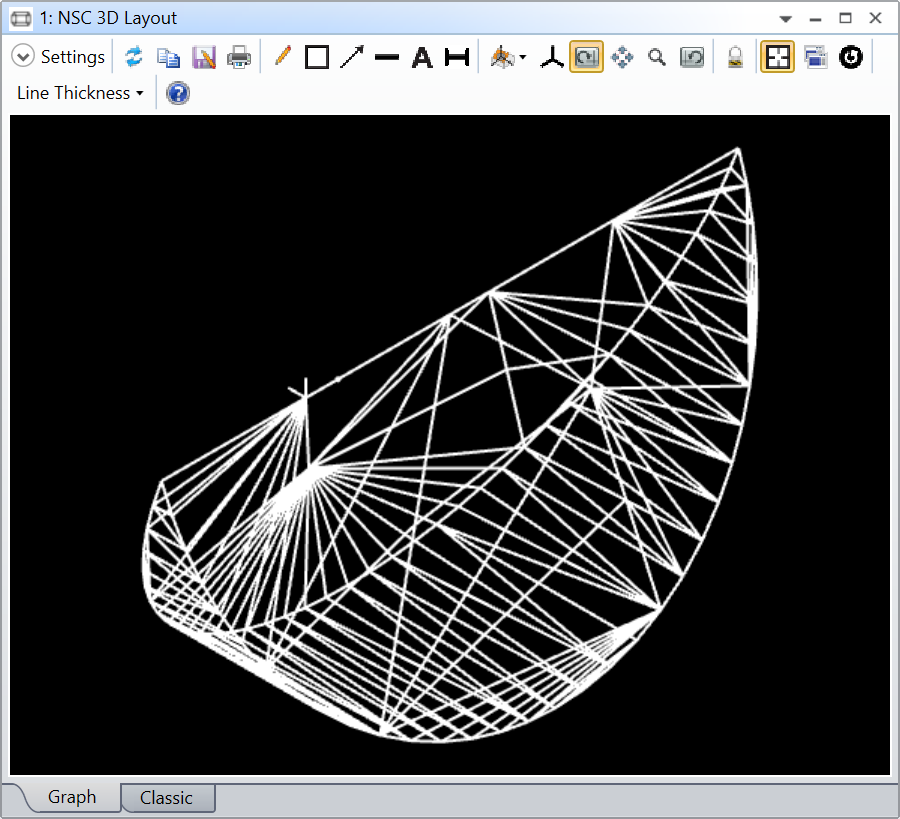
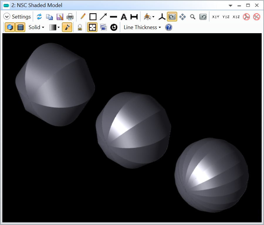
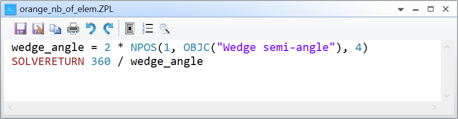
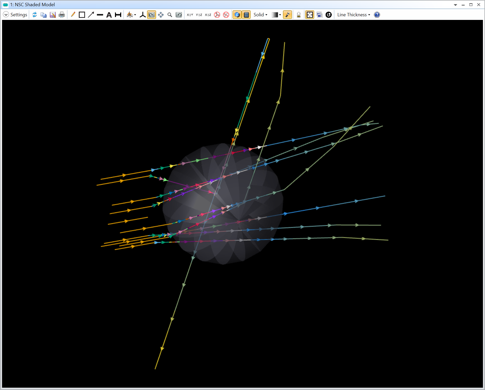
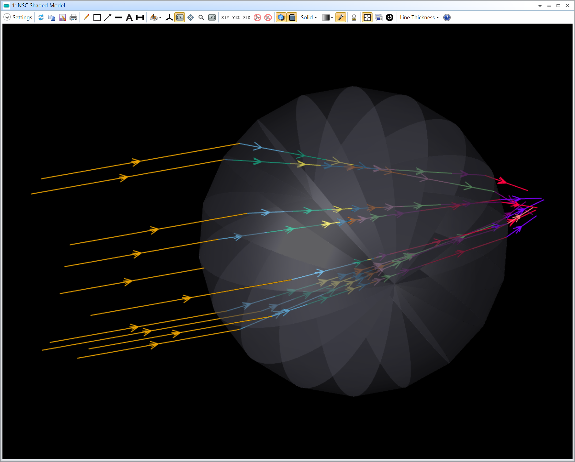
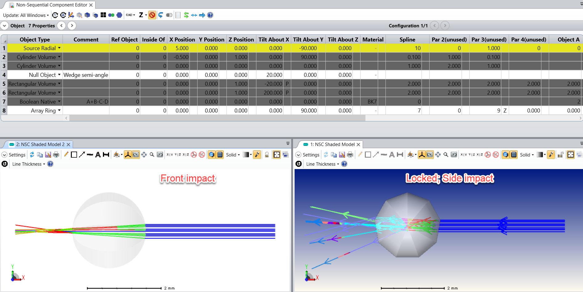
I hope you can see the local axis on the left-hand side of the figure with a small arrow (indicating the Z Axis) pointing along the straight line of the wedge. From then on, you can simply use the Array Ring object. The Radius is zero because you want to rotate exactly about the Local Z Axis, and the # Of Elements is 360 divided by the angle of the wedge. I’ve done an example (also attached to my post) below with 3 configurations showing wedge angles of 20, 40, and 60 degrees:


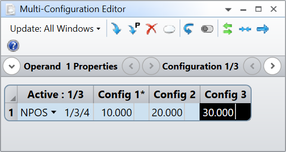
I’m using a macro solve to return the number of elements

It will of course not work if you choose a wedge angle that doesn’t split the orange in discrete wedges.

Thank you for the great question, I had a lot of fun and I hope this solves your problem.

Take care,


David

Userlevel 2
Badge +1

Awesome!  Thank you!!!

Userlevel 7
Badge +3

Stunning answer, David!

Userlevel 2
Badge +1

I’m getting only geometry errors when I try to raytrace the orange with the single raytrace tool.  It appears that Zemax isn’t sure what interface properties to assign between the wedges. 

If you look at the coating properties for the single wedge, there are 11 faces, each with properties defined by a face on the parent cylinder or one of the rectangular volumes that were used to cut the wedge.

Is there some way to tell it to use the same index at the wedge interfaces as that assigned to the wedge itself?

Thanks!

Userlevel 2
Badge +1

Another puzzle is why the rays bend refractively in the air outside the orange.  I’ve only assigned a refractive index to the Boolean wedge.  It seems like there may be a mismatch between the geometry that Zemax created vs. what it’s rendering.


Userlevel 7
Badge +2

@Donna.Waters


TL;DR use Boolean CAD instead of Boolean Native


Unfortunately, the same happens for me:

I had to increase the System Explorer..Non-Sequential..Maximum Nested/Touching Objects to 50. When I look at the single wedge and even without the dummy cylinder, this is what I get:

Somehow a segment is created before the wedge (blue). I was quite puzzled so I wrote a script to automate the creation of the orange as many wedges that I turn and reposition accordingly.

import math

TheNCE = TheSystem.NCE

wedge_radius = TheNCE.GetObjectAt(1).ObjectData.__implementation__.FrontR
wedge_angle = 2*TheNCE.GetObjectAt(2).TiltAboutX

number_of_wedges = int( 360 / wedge_angle )

ref_object_id = 5

for ii in range(1, number_of_wedges):
TheNCE.CopyObjects(ref_object_id, 2, TheNCE.NumberOfObjects+1)

reference_object = TheNCE.GetObjectAt(TheNCE.NumberOfObjects-1)
new_wedge_object = TheNCE.GetObjectAt(TheNCE.NumberOfObjects)

new_wedge_object.RefObject = TheNCE.NumberOfObjects-1

rotation_angle = ii * wedge_angle
reference_object.TiltAboutX = rotation_angle

new_wedge_object.YPosition = math.sin(rotation_angle/180*math.pi)
new_wedge_object.ZPosition = - ( 1 - math.cos(rotation_angle/180*math.pi) )

And this is the result:

I will attach the file to my answer, but this also doesn’t make sense and the rays bend outside the orange. There’s a really odd diagonal ray as well… I tried changing the System Explorer..Non-Sequential..Glue Distance In Lens Unit to 1E-3 (maximum I could set), but nothing changed.

I have a feeling the problem is with the Boolean Native. In fact, if I do the same with Boolean CAD it works for both methods Array Ring and the manual creation and relocation of wedges:

You may want to ask Zemax Support about why it doesn’t work with the Boolean Native 🤔 as an academic, I can no longer log support tickets. Perhaps the Zemax CAD expert @Flurin Herren knows?

I would stick to the Array Ring method but use a Boolean CAD.

Take care,


David

Userlevel 7
Badge +3

Definitely think Zemax support should look at this, it looks very much like a bug that’s spoiling an otherwise excellent application of killer features!

  • Mark
Userlevel 2
Badge +1

It does seem to be working with the Boolean CAD object.  Thanks so much for all your help!

Userlevel 7
Badge +2

Out of curiosity, can you tell us what you'll use the orange for @Donna.Waters ?

Userlevel 2
Badge +1

I can’t, but I can share this orange joke:

What happens when you rub two oranges together?

Userlevel 2
Badge +1

Hint: Consider classical mechanics, as well as what an orange consists of.

Userlevel 7
Badge +3

 I like the Boolean Native / Array Ring model generated by @David.Nguyen; very clever!

The ray-tracing issue associated with this version is likely related to the placement of the source.  As noted in the help documentation for the Boolean Native object, if the source is located inside one of the parent objects, then the source should have the “Inside Of” parameter set to the Boolean Native object number (which may require changing the row at which the source is defined in the NCE).  Otherwise, rays will refract at the boundaries of the parent object(s).


Alternatively, for a collimated source, its origin can simply be moved outside of any parent objects.

Using the single-slice example above, you can see two different results depending on where the source is positioned:


Regards,

Jeff

Userlevel 7
Badge +3

Ok, as a follow-up to the previous post, there does indeed to be some strange behavior when the array ring object is used to combine the slices, even when the source lies well outside of the parent volumes:


It would be helpful for someone at Zemax to take a look.

Userlevel 7
Badge +2

Thank you for the insight @Jeff.Wilde. I had forgotten about this peculiarity of the Boolean Native (vs Boolean CAD). It solves part of the problem at least.

I want to hear the orange joke @Donna.Waters, I’m thinking heat and juice but I still don’t get it 😅

Take care all,


David

Userlevel 2
Badge +1

@David.Nguyen  You’re on the right track, but it’s not “juice heat”...

Userlevel 4
Badge +1

I can’t, but I can share this orange joke:

What happens when you rub two oranges together?

Frictic Acid?

Userlevel 2
Badge +1

You’re both on the right track.  It’s both a literary genre and a hit movie...

Userlevel 6
Badge +2

As a hint, it’s considered a cult classic movie from 20+ year ago.

P.S.  I had to think about this one a bit, so thanks for the brain teaser @Donna.Waters 

Badge +3

Hi all,

Hope you are doing well and thanks for looping me in here, @David.Nguyen. This is the Zemax Forum at its best. Unfortunately, I don’t have an orange pun to contribute.

I`ve tried to reproduce all the points which were raised here.

Single slice;

Weirdly enough, if I delete the Array Object and only look at a “single slice” which David has created with the Boolean Native, there is still a ghost segment before the ray is entering the body (Marked in the right NSC Plot in red below). But if I turn the slice 90 degrees and enter the body from the top, the rays seem to propagate correctly into the slice, but still have a odd behavior exiting it.

As already mentioned in this thread, the Boolean CAD seems to work:


Full orange;

If we look at the front and side impact for the full orange, we can see that the behavior (bug) agrees with the findings from the single slice. As we established in the single slice example, the impact from the outer (“orange skin side”) does not create a ghost segment in the front, but after the propagation through the orange:


@Donna.Waters , I can see that you have already opened a case via our support channels. My colleague Navreen is currently filing an internal bug report, so the Dev`s can take a look at this.

Thanks everyone for all the contribution!

We will keep you updated.

Userlevel 7
Badge +2

Hahaha, I think I got the joke finally with @Sean Turner and @MichaelH’s help 😄 Thanks for sharing this one @Donna.Waters and thanks for the feedback also @Flurin Herren.

Take care all,


David

Userlevel 4
Badge +1

Of course! Thanks for the laugh @Donna.Waters 

Reply