I am using the built-in sample "Laikin 100 Degree WFOV" sequential design to pathfind Zemax capabilities.
I am trying to simultaneously model the effects of mechanical sag and thermal expansion and contraction on the optical system as a whole. I have already successfully accomplished the latter using a Multi-Config setup I obtained by pressing the "Make Thermal" button and editing the result to suit my scenarios.
If I then tilt all surfaces besides Object and Image by the same amount (say, 0.1 degrees about X), according to the grid distortion output, the boresight ray still impinges on (0, 0) on the image plane, which makes no sense to me. That boresight ray ought to be hitting the image plane at an offset of around EFL * tan(0.1 degrees) from (0, 0).
Something I have read in the Knowledgebase suggested that I should try this stunt in global coordinates to get the expected result. However, when I try to convert from Local to Global Coordinates, I get this error:
Does that mean I can model multi-config thermal effects, or mechanical (tilt) effects, but not both at the same time?
My Zemax version is OpticStudio 19.8 Professional 64-bit, running on Windows 10.
Daniel
Best answer by Hui Chen
Hi Daniel,
Now let me address the second issue you had regarding usage of the Local To Global conversion tool. The reason you encountered the error message was because OpticStudio does forbid using this feature when there are Coordinate Break surfaces appearing within the range you trying to convert to global coordinates. This is stated in the Help File, "This feature is not supported if any coordinate break properties within the range are controlled by the multi-configuration editor.". The reason is because this Local to Global conversion tool works by adding multiple CB surfaces to your system to place each surfaces referenced to the Global Coordinate Reference Surface specified under System Explorer. If your system already have CB surfaces built in, and that CB surface is controlled by the Multi-configuration editor, then this Local to Global converter will not be able to make changes to that CB surface, therefore, not working properly.
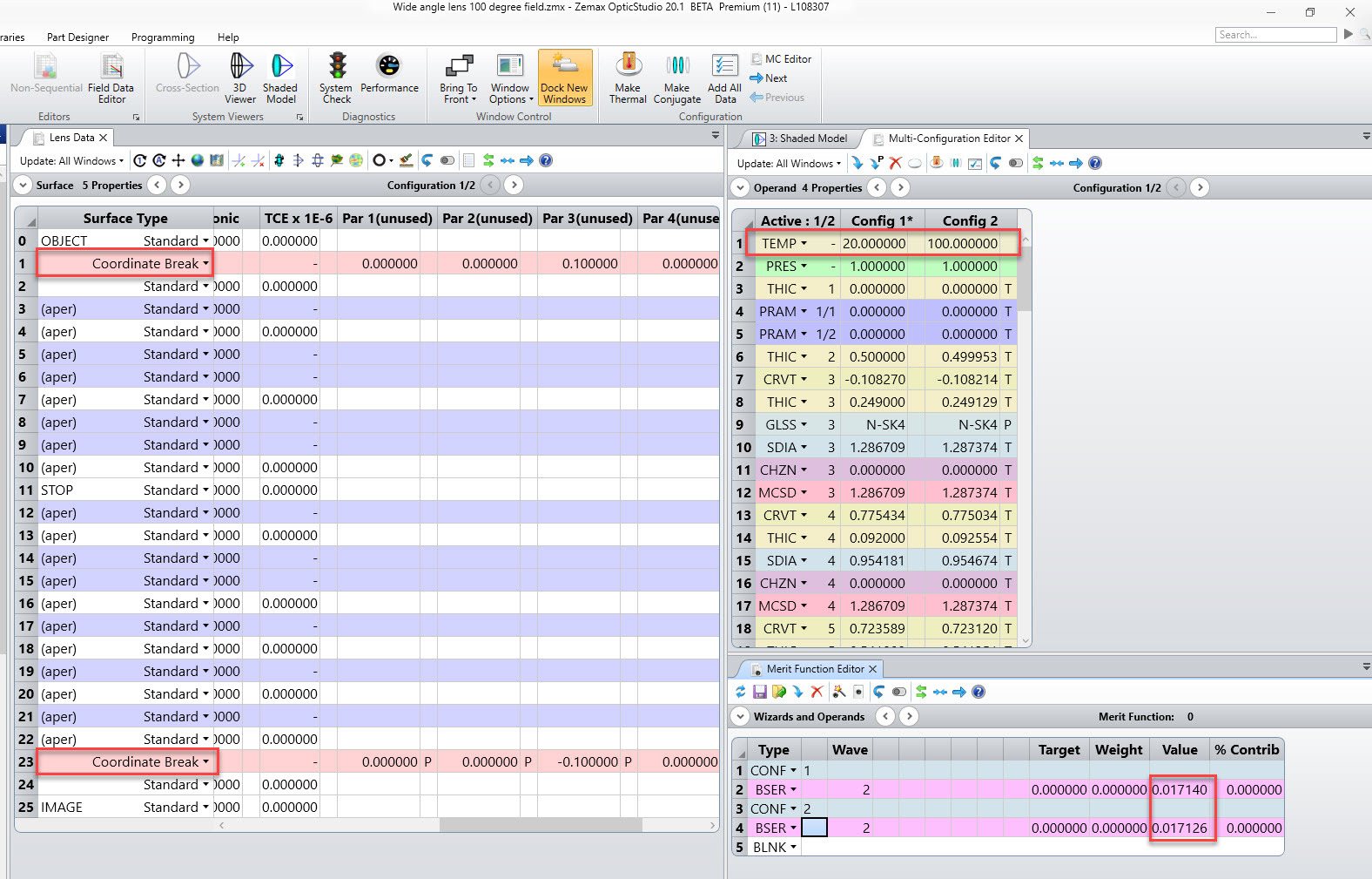
In this case, you don't need to use the Local to Global tool. You can stay in the local coordinate system, add the CB in for your tilt x, create your multi-configuration system using Make Thermal, and observe the boresight error using BSER. Below i've shown a two config system with config 1 at 20C and config 2 at 100C.
Do you think this approach works for you to evaluate the thermal effects in your design?
Hui
I don't know why the image of the error dialog box I posted didn't "take."
However, that error dialog box just contained the verbiage in the title of this thread. I assume that the "my" is a typo in the error message, and that it should say "by multi-config operands" instead.
Let me break this into two separate issues. This post is to address only the first question you posted, that when you tilt all the optics in the Wide angle 100 degree lens, (while keep the object and image surface as they are), you did not observe a boresight error or a boresight ray shift caused by the tilt. You mentioned you were using the Grid Distortion output to observe the movement of this boresight ray. I assume you are referring to the Text tab of the Grid Distortion analysis and saw Predict XY and REAL XY all remain zero for the (0,0) degree field. If this is the case, I need to clarify that the Grid Distortion is not a tool intended for this purpose, because the Predict and Real XY are not the "absolute" ray intercept coordinates on the Image plane, rather, they are relative position referenced to certain field point chosen under the Settings drop down. This is described in the Help File about the Grid Distortion, "and the subscripts r and p refer to the real and predicted coordinates on the image surface relative to the reference field position image location, respectively."
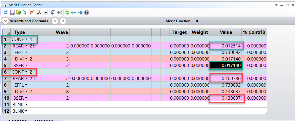
The way I would recommend to look at this boresight ray shift is to use operand REAR for the on-axis chief ray to return its radial position on the image plane. And this REAR radial position is in fact referenced to image surface vertex, so you can observe the boresight error. Below in the Wide 100 deg lens file, I made it a two configuration where config 1 is the nominal system, and config 2 is the 0.1 tilt about X system you mentioned. I added the REAR operands to return the on-axis chief ray radial position on the image plane, and you can observe a clear change between conf1 and 2 due to the tilt. OpticStudio also has an operand BSER, Boresight Error, which is
defined as the radial chief ray coordinate traced for the on axis field divided by the effective focal length. This BSER operand directly gives you the boresight error.
Now let me address the second issue you had regarding usage of the Local To Global conversion tool. The reason you encountered the error message was because OpticStudio does forbid using this feature when there are Coordinate Break surfaces appearing within the range you trying to convert to global coordinates. This is stated in the Help File, "This feature is not supported if any coordinate break properties within the range are controlled by the multi-configuration editor.". The reason is because this Local to Global conversion tool works by adding multiple CB surfaces to your system to place each surfaces referenced to the Global Coordinate Reference Surface specified under System Explorer. If your system already have CB surfaces built in, and that CB surface is controlled by the Multi-configuration editor, then this Local to Global converter will not be able to make changes to that CB surface, therefore, not working properly.
In this case, you don't need to use the Local to Global tool. You can stay in the local coordinate system, add the CB in for your tilt x, create your multi-configuration system using Make Thermal, and observe the boresight error using BSER. Below i've shown a two config system with config 1 at 20C and config 2 at 100C.
Do you think this approach works for you to evaluate the thermal effects in your design?
Hui
Is there any way to make the entire Grid Distortion output (both predicted and real) adjust to the errored boresight ray in the second configuration? In other words, I need the real and predicted image points corresponding to (i, j) = (0, 0) to match the (x, y) values that led to the calculation of REAR. Note that a scalar radial error doesn't help me; I need the 2D vector offset for where that boresight impinges on the image plane, and I need it to not just adjust the boresight, but also, *all* the grid points.
If not, then this approach does not solve my problem. I need to be able to generate a raytrace table that shows (a) what the input rays were with respect to the input boresight ray, and (b) what the corresponding points were on the image plane, with respect where the boresight ray would have landed in the non-tilted configuration.
It is starting to sound like Zemax can't do this, and that I will have to do some post-processing to adjust those impinging point locations after i import them into Matlab.
I may have discovered a way to do this as a post-process. Through some trial and error, I have discovered that the 'Xref = ' and 'Yref = ' values in the Grid Distortion text output are moving in ways that are consistent with how I would expect the intersection of the boresight ray with the image plane to move, given X and Y tilts of the internal optical chain.
I think I can just add these values to the real and predicted X-Y positions of those grid points to get what I need ... as long as that (Xref, Yref) vector represents what Zemax subtracted from all the X-Y grid positions, in order to re-reference them back to the boresight ray's image point.
I will perform some further analysis to see if that is the case, and report back here.
Is there a way for me to edit the title of this thread?