Solved

Construction of a first-order microscope and check the size of the object field

  • 15 September 2022
  • 2 replies
  • 295 views

Userlevel 1

Hello Zemax community!

I am an optics postgrad from New Zealand. I am not major in lens design, but genuinely interested in developing paraxial lens knowledge. I have been learning and following OpticsRealm (created by Scott) tutorial on youtube. Unfortunately, that because his tutorial was recorded over 10 years ago, it is not possible to find any solutions.  

I put the question from Scott below in BOLD, and followed by my answer. I am sure some of the Pros at this community can spot some rookie issues with my approach. If you can teach me that what an optical engineer would handle this in Zemax? Massive thanks. 


Refine construction of a first-order microscope in Zemax:

  • Utillize paraxial lenses
  • Infinity corrected with 200mm tube lens
  • objective lens f=20mm
  • 8 mm diagonal sensor (1/2’’ CCD)
  • NA of 0.2

What is the size of object field?


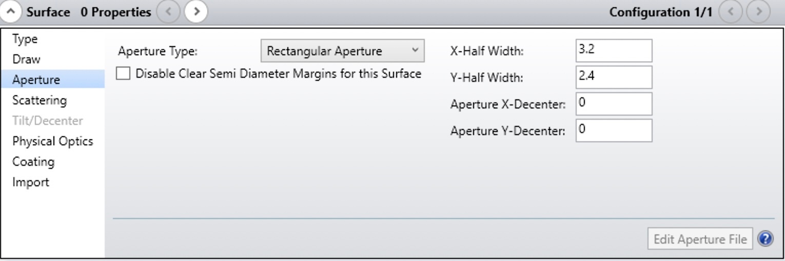
(1) I planned to work “Backward” in this microscope system from 1/2’’ CCD to Tube lens, aperture stop then to the objective and finally the sample/object. The 8mm diagonal sensor has width and height of 6.4 and 4.8 mm, respectively. I chose the Surface 0 and set the Aperture to be “Rectangular”. With X-half and Y-half widths 3.2 and 2.4mm. ( I noticed that here once the rectangular is chosen, the “cross-section” diagram is no longer available. Probably it makes sense as the object/image is in 3D)

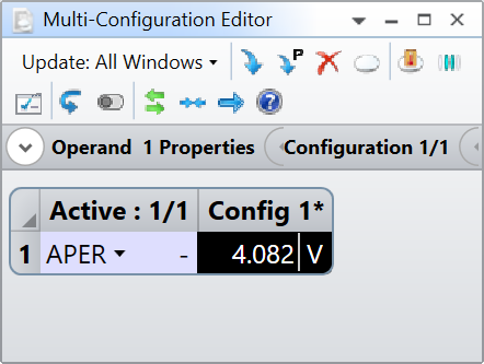
(2) With NA=2 and objective focus f=20mm. I worked out the aperture diameter in this system to be ~8.16 mm using the formula (from wiki):

The semi-diameter of the aperture therefore should be 4.08 mm as entered in surface 2:

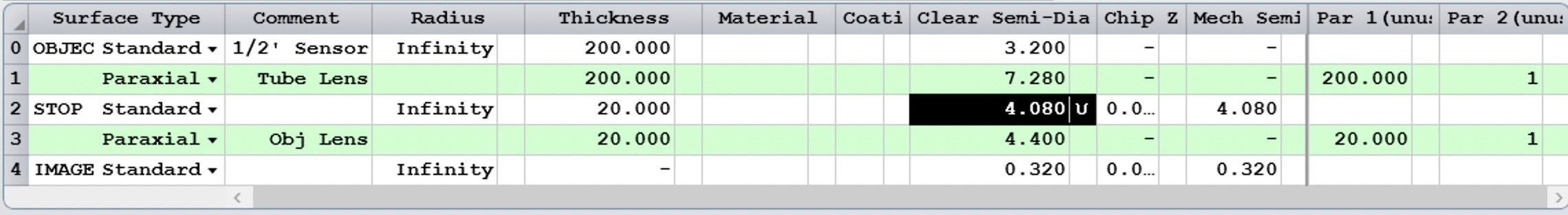
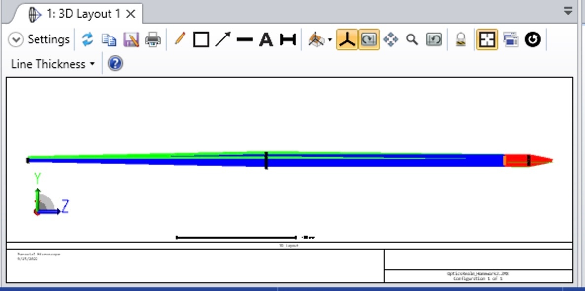
(3) The other surfaces (paraxial lens) are also set up as the figure above. I am not showing a very nice 3D layout here as I am not quite sure how to nicely zoom in in y-axis in this 3D layout...Just put a screenshot below:

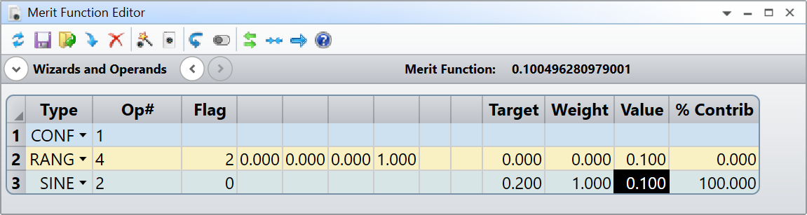
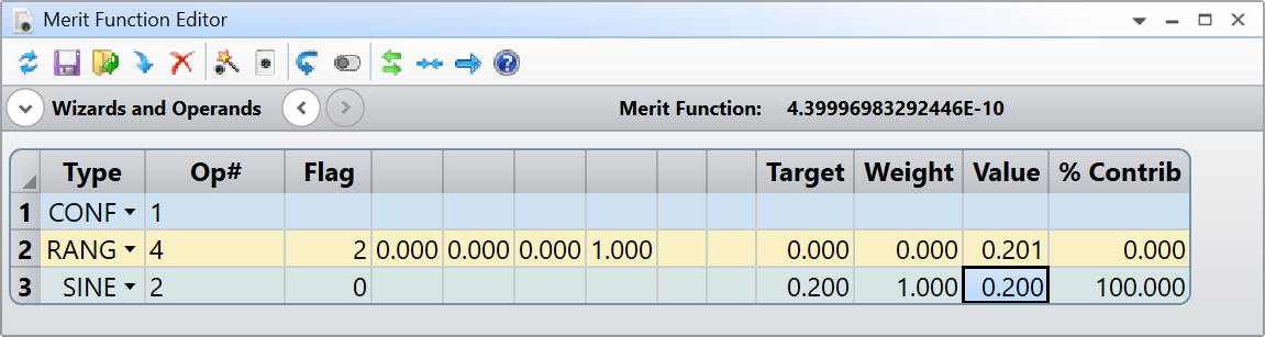
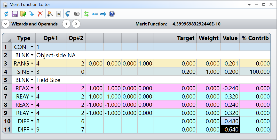
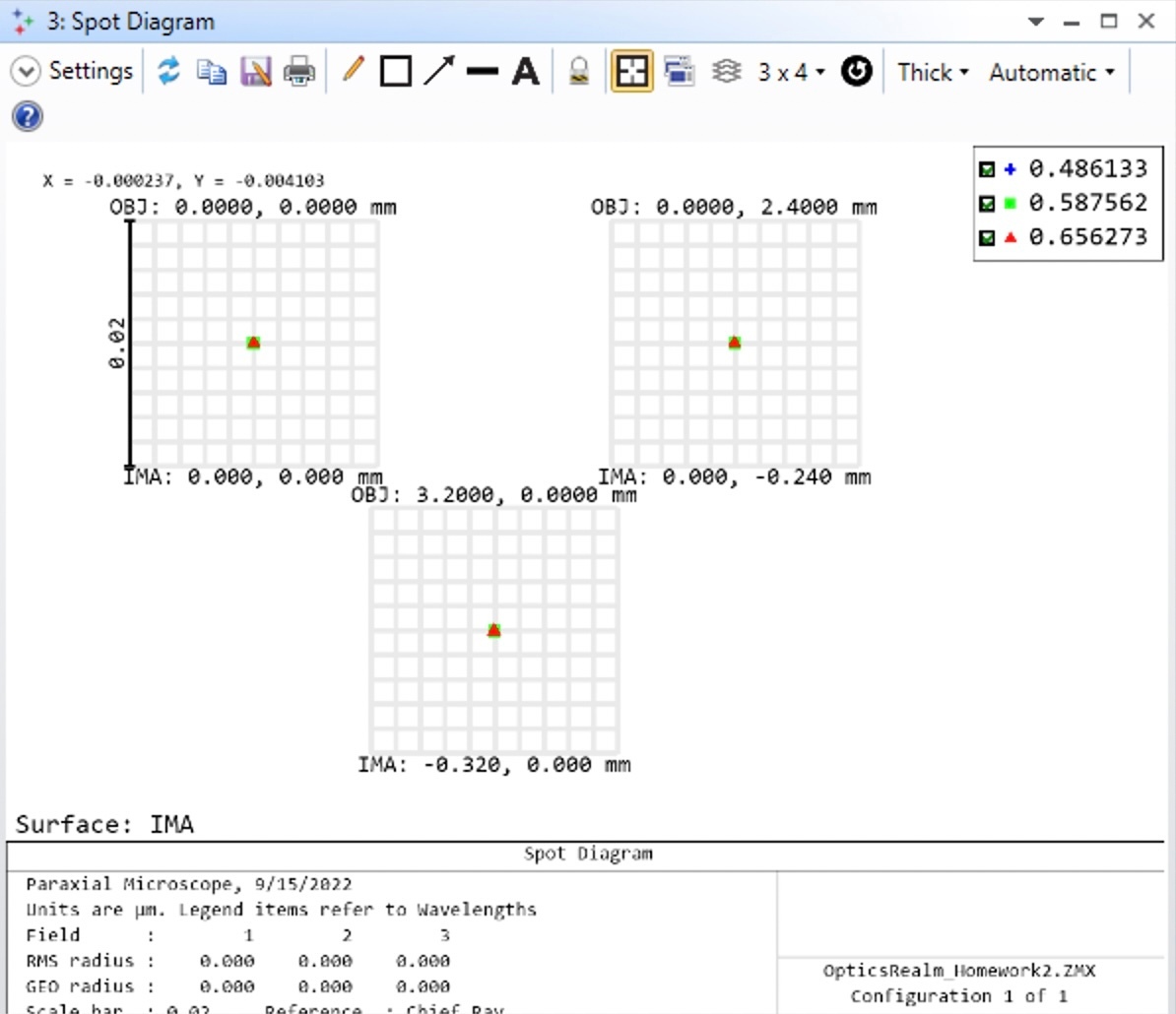
(4) The final step here is trying to find out what is the object field size. I have tried few methods, but this one is what I think a bit easy for me. Obviously, this microscope system as a magnification of 10. So I can work out the field size numerically. But it would be nice the Zemax raytrace can confirm. I chose the “standard spot diagram”. It gives the image -0.32 and  -0.24 mm. It means that the size is a rectangle of 0.64 x 0.48 mm object.


[Mod note: moved to more appropriate forum for OS-related discussions.] 

icon

Best answer by David.Nguyen 15 September 2022, 18:26

View original

2 replies

Userlevel 7
Badge +2

Hi Yadong,


I think what you did is great, and I don’t have much to add. OpticStudio might be an overkill to answer the question, but at least you get to practice a little bit. As you said, you know the magnification from the ratio of the tube lens over the objective lens (200 / 20 = 10X), so the object field is the sensor size divided by the magnification. A 1/2” sensor has a dimension of 6.4 x 4.8 mm square, if you divide each dimension by 10 you get your 0.64 x 0.48 mm square.

Maybe two things I can suggest. First, you used Wikipedia to workout the NA of your system on the image side in OpticStudio (which is your object-side because you modeled the microscope backwards). This is great, but you could have done it in OpticStudio using the Merit Function. By default, OpticStudio will not let you make the STOP surface Clear Semi-Diameter as a variable. However, if you use the Multi-Configuration operand APER, it allows you to set it as a variable (more details in this article):

Then, in the Merit Function, you can use the operands RANG, and SINE to compute the sine of the marignal ray (Hx = Hy = Px = 0, and Py = 1), which is your NA (you could also add the operand INDX and PROD if you need to factor in the refractive index):

Notice the target value of 0.2 for the SINE operand, which is your NA on your object-side. If we run the optimization we get:

An aperture semi-diameter of 4.082 as you previously calculated but this time all in OpticStudio.

Second, you could also use the Merit Function with the operands REAX, REAY, which give a ray X, and Y position respectively, and DIFF, which calculates the difference between two operands to retrieve the field size:

Hopefully that sort of makes sense. Based on what I showed you, can you retrieve the magnification from the Merit Function?

Take care,


David

Userlevel 1

Hi Yadong,


I think what you did is great, and I don’t have much to add. OpticStudio might be an overkill to answer the question, but at least you get to practice a little bit. As you said, you know the magnification from the ratio of the tube lens over the objective lens (200 / 20 = 10X), so the object field is the sensor size divided by the magnification. A 1/2” sensor has a dimension of 6.4 x 4.8 mm square, if you divide each dimension by 10 you get your 0.64 x 0.48 mm square.

Maybe two things I can suggest. First, you used Wikipedia to workout the NA of your system on the image side in OpticStudio (which is your object-side because you modeled the microscope backwards). This is great, but you could have done it in OpticStudio using the Merit Function. By default, OpticStudio will not let you make the STOP surface Clear Semi-Diameter as a variable. However, if you use the Multi-Configuration operand APER, it allows you to set it as a variable (more details in this article):

Then, in the Merit Function, you can use the operands RANG, and SINE to compute the sine of the marignal ray (Hx = Hy = Px = 0, and Py = 1), which is your NA (you could also add the operand INDX and PROD if you need to factor in the refractive index):

Notice the target value of 0.2 for the SINE operand, which is your NA on your object-side. If we run the optimization we get:

An aperture semi-diameter of 4.082 as you previously calculated but this time all in OpticStudio.

Second, you could also use the Merit Function with the operands REAX, REAY, which give a ray X, and Y position respectively, and DIFF, which calculates the difference between two operands to retrieve the field size:

Hopefully that sort of makes sense. Based on what I showed you, can you retrieve the magnification from the Merit Function?

Take care,


David

Massive thanks to your detailed suggestions. The merit function is what I am trying to learn. Will try your method later tonight, might even try with some stock components in the lens library just to check that how it can help to optimize the field curvature. Thanks again David! Take care.  

Reply