I imported CAD objects on NSC mode, but the the objects are overlapping no matter the X, Y, Z coordinates I am setting. Is there any method to properly place the objects?
[Mod note: moved from OpticsBuilder User Group to general “Got a Question” forum as this pertains to OpticStudio’s CAD import]
Best answer by David.Nguyen
Hi Priscilla,
I’m not sure I really understand the problem. Are you saying that when you change the Z Position of one of the CAD Part, this part isn’t actually moving in the Shaded Model? This shouldn’t be the case though.
I know it can be tricky to position CAD objects accurately if their reference coordinate system isn’t known. Let me show you an example and you tell me if it rings a bell.
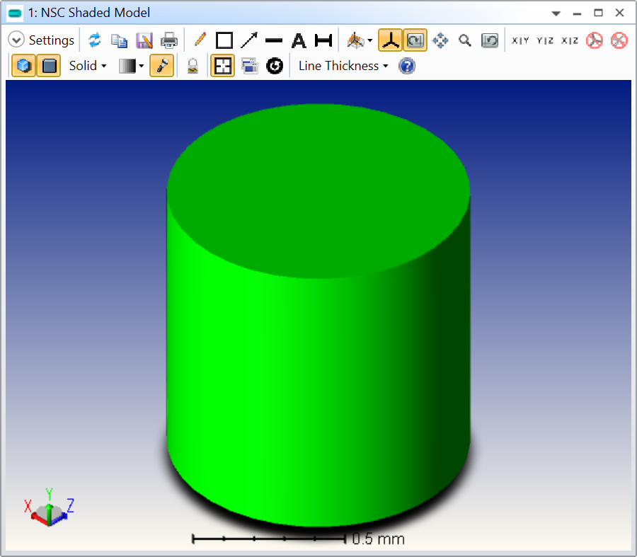
I have used solidworks to create a dummy cylinder STEP file that I imported in OpticStudio with X = Y = Z = 0.0 mm. Here is what it looks like:
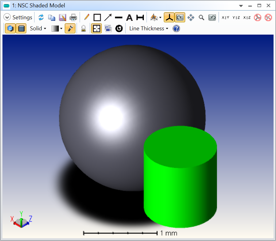
So far, so good. Now, let me add a Sphere to my Non-Sequential Component Editor with the same coordinates (X = Y = Z = 0.0 mm). Here is the result:
As you can see, despite these two objects having the same X, Y, and Z Positions, they are not located in the same place. The key is in how I generated the STEP file, but before I go into more details, let’s just try the following:
I’ll remove the Sphere
Double-click on my CAD cylinder in the Non-Sequential Component Editor
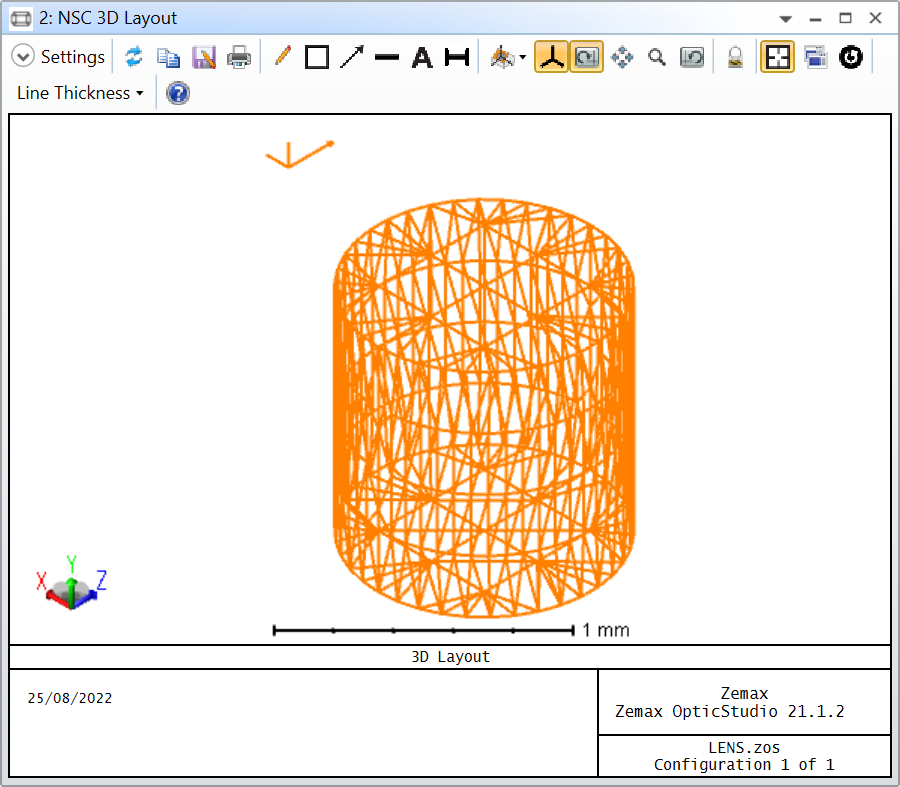
Go to the Draw tab, and press Draw Local Axis
Open a 3D Layout
Here is the result:
At the top-right of the cylinder, you see the local axis appeared in orange. This is the actual location X = Y = Z = 0.0 mm. It is outside of the cylinder! This is because OpticStudio continues to use the same reference axis that was used to generate the object in your CAD software.
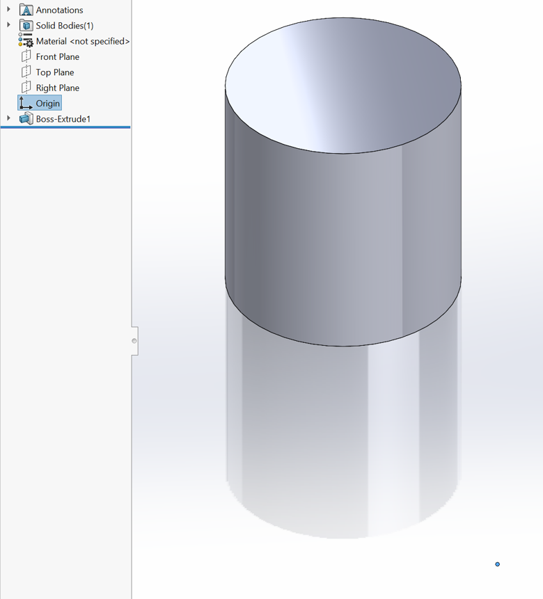
In my example, in Solidworks, I can click Origin in the Part tree, and the origin shows as a blue dot at the bottom-left of the cylinder:
In order to properly place your objects, you need to know where that origin is in your CAD files otherwise it gets quite complicated. Does that make sense? Is that the issue you are having?
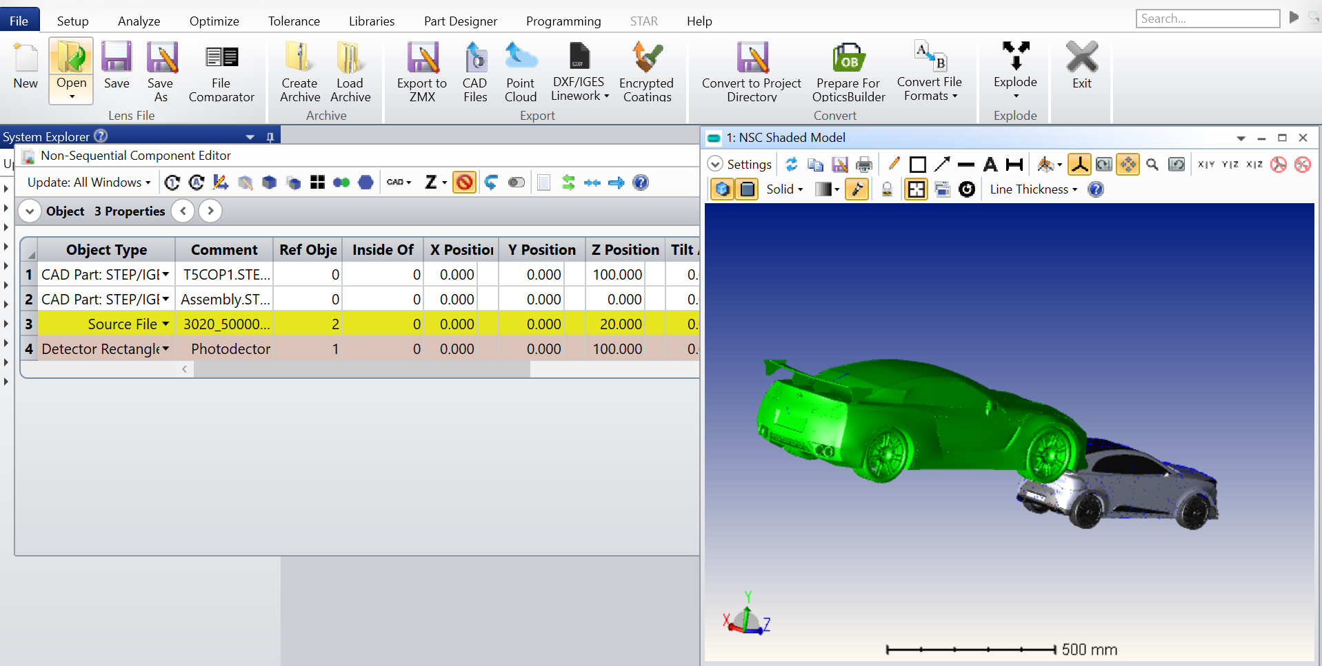
Thank you for responding, here is the snap of what I get up on importing CAD objects, despite the difference on Z coordinates the objects appears as they are on the same location.
I’m not sure I really understand the problem. Are you saying that when you change the Z Position of one of the CAD Part, this part isn’t actually moving in the Shaded Model? This shouldn’t be the case though.
I know it can be tricky to position CAD objects accurately if their reference coordinate system isn’t known. Let me show you an example and you tell me if it rings a bell.
I have used solidworks to create a dummy cylinder STEP file that I imported in OpticStudio with X = Y = Z = 0.0 mm. Here is what it looks like:
So far, so good. Now, let me add a Sphere to my Non-Sequential Component Editor with the same coordinates (X = Y = Z = 0.0 mm). Here is the result:
As you can see, despite these two objects having the same X, Y, and Z Positions, they are not located in the same place. The key is in how I generated the STEP file, but before I go into more details, let’s just try the following:
I’ll remove the Sphere
Double-click on my CAD cylinder in the Non-Sequential Component Editor
Go to the Draw tab, and press Draw Local Axis
Open a 3D Layout
Here is the result:
At the top-right of the cylinder, you see the local axis appeared in orange. This is the actual location X = Y = Z = 0.0 mm. It is outside of the cylinder! This is because OpticStudio continues to use the same reference axis that was used to generate the object in your CAD software.
In my example, in Solidworks, I can click Origin in the Part tree, and the origin shows as a blue dot at the bottom-left of the cylinder:
In order to properly place your objects, you need to know where that origin is in your CAD files otherwise it gets quite complicated. Does that make sense? Is that the issue you are having?
Thank you so much for your prompt response; I was confused by the concept of coordinates in the origin file. The information you provided is extremely useful.
I have similar troubles when importing CAD objects in Zemax. The tip to draw local axis is extremely usefull, as it allows to locate the origin of a part
Which raises the questions :
is there a reason that local axis are not drawn in NSC Shaded model and only in NSC 3D Layout ? I found using Shaded model view is convenient to visualize alignment and ray traces, so having the local axis of each object would be nice
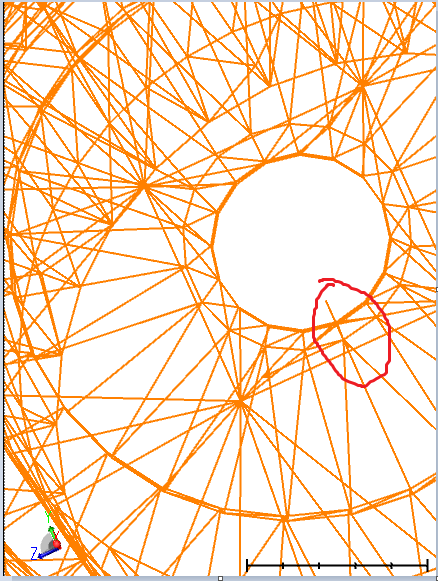
Is there a way to make the local axis more visible (bigger ? bolder ? colored ?) because when the CAD object is a bit complex and the local axis is somewhere close to it, it is difficult to locate it - see the attached example where the local axis is drawn and difficult to see (in other words, if don’t already known where about to look for it, it is quite difficult to distinguish it from the part)
As far as I know, none of what you suggest is possible yet, unfortunately.
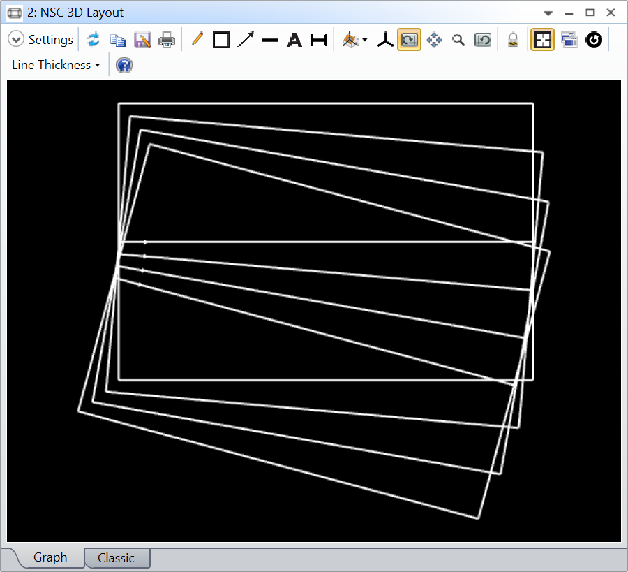
Another trick I use sometimes to help me with such issues is to use the Multi-Configuration Editor (MCE) and apply a gradient of value for a given degree of freedom.
For example, this is a cylinder that I rotated by 0 to 15 degrees by steps of 5 degrees in the MCE, and I display all the configurations in the settings of the NSC 3D Layout.
When I do that, I can see that the object is not rotating about its origin and it gives me a sense of where the center of rotation might be. Of course, in this dummy example it doesn’t make sense to use such approach, but with complex CADs of unknown origin, it sometimes helps.
I guess the origin of a CAD part could be mined from the CAD file itself, but I don’t know how to do that.
I found another workaround, heavy and ugly but does the job : I add a rectangular detector and 3 source ray that are referenced into the said CAD object so that it creates a visual CS centered and oritented at the origin of that CAD object - also displays it in the shaded model so that’s nice
Still, it cluters the editor with many rows for not much
We use 3 different kinds of cookies. You can choose which cookies you want to accept. We need basic cookies to make this site work, therefore these are the minimum you can select. Learn more about our cookies.