I want to optimise a design with a birefringent wedge. At least one of the surfaces ( input or output ) is tilted, this tilt changes dependent on an optimisation but I want keep the optical axis at 45 degrees to the z axis. Am not sure a ZPL Solve is working correctly ( might be my code!? ) - is this the correct way to control the optical axis during an optimisation? Else, any pointers welcomed

Solved
Birefringent Wedge with Tilted Input - Optimisation
Best answer by Hui Chen
I see you have sent in a support ticket on this topic. I have just replied on that ticket. But I’ll post the suggestion here as well so people on the forum can comment if there is a better way of achieving this. I used ZPL macro solve to do this. If you want to keep the same crystal axis orientation while freely tilting the front surface during optimization, you will have to "counter tilt" the crystal axis back with the same amount, calculate the new direction cosine in the ZPL, (since those crystal axis direction cosines are defined using surface local coordinates), and then apply ZPL macro solve to set the new direction cosine values. Depending on how complex the tilt you wanna introduce during optimization, this "tilt back" operation could get fairly complicated to calculate. Below is just a simple example to demonstrate how this process works. The crystal axis starts with an orientation in the YZ plane with a 45 deg angle with both the Y and Z axes. The plate is not wedged at first. Later during optimization let’s assume a 20 deg Tilt About X was introduced. If I don't change the direction cosines of the crystal optical axis, the axis will now form a 45-20=25 deg angle with the horizon. If I want to keep the 45 deg between the crystal axis and the horizon, I need to enter Z direction cosine for 65 deg, because that is the new angle between the crystal axis and the tilted local Z axis. I can do all these operations within the ZPL macro and then use SOLVERETRUN to return the new Y and Z direction cosines to the Lens Data Editor. Now in this example below, you can see after I apply the ZPL macro solve on the Y and Z direction cosines, the crystal axis remains the same between conf 1 (unwedged plate) and conf 2 (wedged plate). And I can change the Tilt About X angle from 20 to 10, and the crystal axis still remains 45 deg with the horizon. 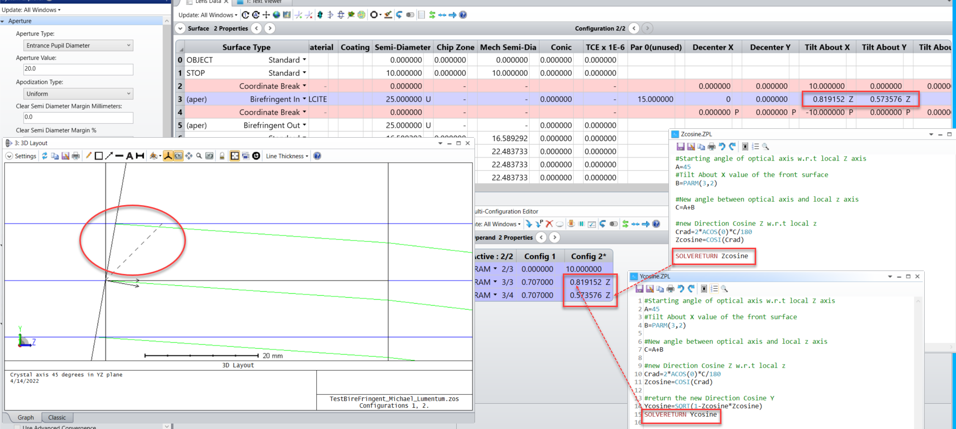
This is just a simple example to demonstrate that this approach could potentially work. If you have a compound tilt, the calculation to figure out the crystal axis direction cosines in the tilted local coordinate system could get complicated. But in general this approach should work. Let me know what you think.

Enter your E-mail address. We'll send you an e-mail with instructions to reset your password.
Need more help?
To Chinese users:
Do not provide any information or data that is restricted by applicable law, including by the People’s Republic of China’s Cybersecurity and Data Security Laws ( e.g., Important Data, National Core Data, etc.).
不要提供任何受适用法律,包括中华人民共和国的网络安全和数据安全法限制的信息或数据(如重要数据、国家核心数据等)。