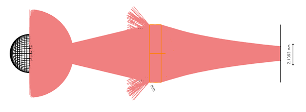
Hi, so I am modelling a simple RED LED and planar convex lens and trying to get it to focus on a detector. I'm am doing this as an exercise to compare to real world results and gain some understanding.
|
Distance from base of bracket, Collimated (mm) |
Real Radius |
Sim Radius |
|
20 |
3 (inner) |
2.6 (inner) |
|
20 |
4-5 (outer) |
8.9 (outer) |
|
80 |
3.45 |
- |
|
100 |
4.9 |
3.5 |
|
120 |
4.9 |
3.7 |
|
180 |
5.4 |
4.7 |
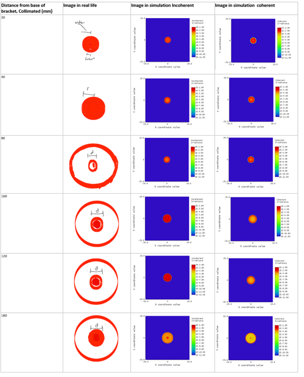
So the tables above shows comparison of real world observations vs. simulation ones ( I have attached a image of the visual comparisions, sketches only rough and light tends to fade in outer rings). Both visual and measured. I would assume the difference in measured radius would be due to inaccuracies/differences in in the physical setup (my setup is quite simple). The trends seem similar. However I am concerned about the additional rings of light visible in real world. I cannot explain these. I am most worried about extra light lost that is not modelled, but would also just like to understand.
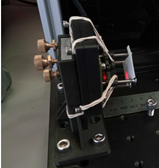
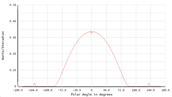
I have also attached images of setup and simulations.
Am I using correct comparision to real world visual, is incoherent or coherent better?
Other concerns:
Is modelling a more accurate wavelength spectrum worthwhile, I am currently using a single wavelength?
I am currently using non-sequential, is this best?


