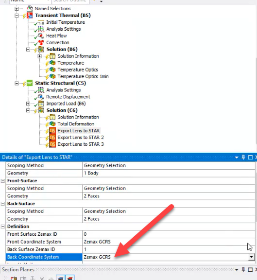
One of the frequent challenges that can occur when using several products during your multiphysics simulation analysis is a mismatch between coordinate systems. Different engineering teams can use tools that use a different Global Reference Coordinate Frame. This leads to a more complicated workflow when different aspects of the project are brought together into one location. One option is to halt the process, go back to the team member, and request a new dataset with an updated coordinate system. Delays can stack up leading to missing project delivery dates. Oftentimes though, you can perform some simple steps to align the coordinate systems to continue progressing and avoid stopping your workflow.
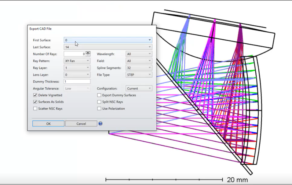
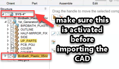
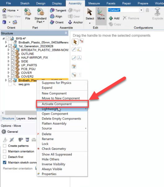
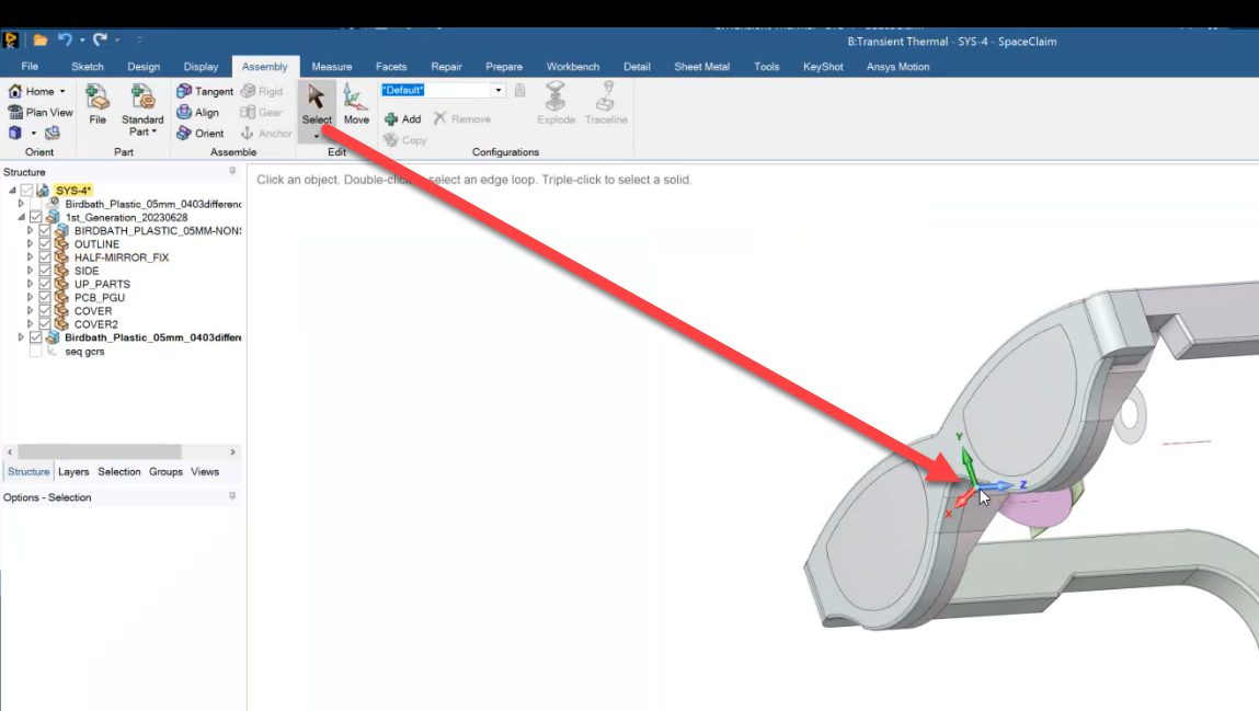
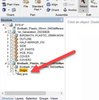
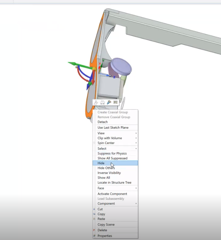
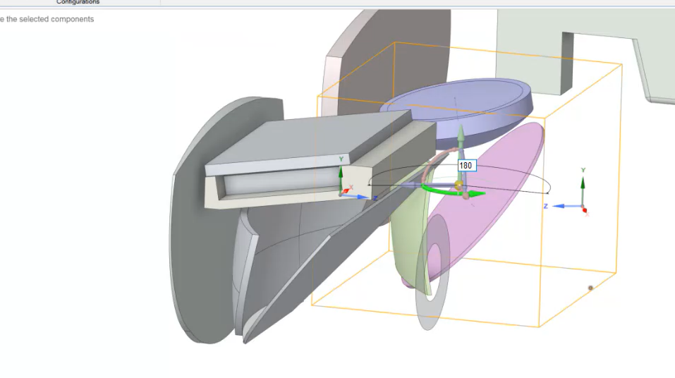
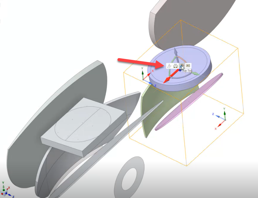
Here we demonstrate some steps you can take when working in Space Claim to match a STEP export from Ansys Zemax OpticStudio into a CAD assembly in an AR/VR headset system. Many thanks to Matthias who figured this out.


