Solved

Achieving desired f-number for a plano-convex lens with a fixed diameter

  • 5 February 2022
  • 2 replies
  • 487 views

Hello, this is my first post! I am hoping someone can help me understand what I might be doing wrong. In my first attempt, I tried to create a plano-convex (pcx) lens with an entrance pupil diameter (EPD) of 5 mm and an f-number of 1.0.

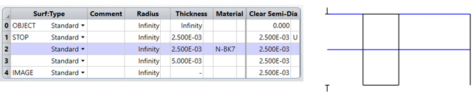
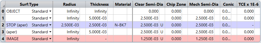
I specified an EPD aperture type and then set its value to 5 mm. I then set the semi-diameters of the first and second surfaces to half the EPD value, and the thickness of the third surface to 5 mm. My thought being that this will give me an f/1 system (see prescription below).

pcx lens prescription

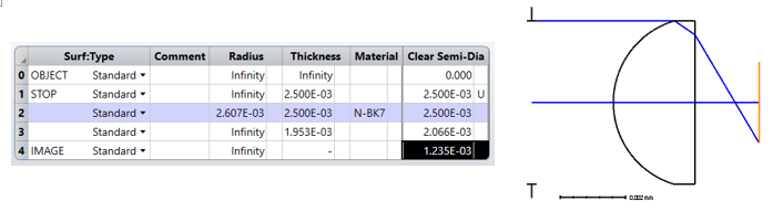
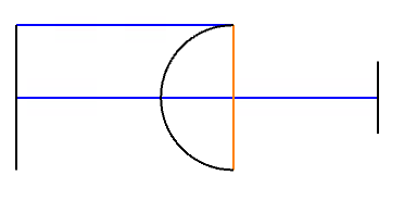
However, from the image below, you can see that the marginal ray is being “clipped.”

pcx lens layout

I verified this by running a single ray trace and sure enough the Real Ray Trace Data for surface 3 says, “Ray terminated, TIR at surface 3.” Also, the Image Space F/#, Paraxial Working F/#, and the Working F/# all report 0.95893. I tried to increase the radius value, in very small increments, and did notice the F/# value increasing slightly, but it never goes above ~0.96. Is there something wrong in my process? I feel like there is something fundamental that I am missing here. Anyways, I look forward to any help.

-Cheers!

icon

Best answer by Mark.Nicholson 5 February 2022, 19:21

View original

2 replies

Userlevel 7
Badge +3

Hey Chris,

That’s the correct answer, As set up, the marginal ray is tangent to the optical surface. Make the surface flat, or at least not spherical and the system will trace.

I have a series of videos at Design Optics Fast - YouTube that will help you understand what is going on and to set up the system correctly.

  • Mark

Hi Mark,

I didn’t realize how quickly you responded. I wish I would have seen this earlier. Thank you for creating such great quality videos! They helped fill some knowledge gaps for me. Top notch.

I did a couple of things following the video you made titled, “How to Optimize the Landscape Lens with Zemax OpticStudio,” which was helpful. Before any optimizations were applied, the aperture type was first set to Float by Stop, while all other parameters were specified using mechanical definitions rather than optical ones. Without any optimizations being applied, the EPD ended up being 0.005 mm, the Image Space F/# was 2e+12, the Paraxial Working F/# & Working F/# were 10,000.

pcx prescription and layout (before optimization)


After applying the F-Number solver to the radius parameter of surface three to be one, the following was attained. The Airy radius is 0.61 um, which is what I expect as the design wavelength was set to 500 nm. However, this doesn’t really fit the pcx profile I was expecting.

pcx prescription and layout (after optimization)

I then attempted to reverse surfaces three and two, and got the following. The Airy radius ended up being 0.3544 um, which doesn’t seem right as this is almost 2x smaller than the diffraction-limited radius of 0.61 um.

pcx prescription and layout (reversing elements three and two)

I then used Quick Focus to optimize for spot size.

pcx prescription and layout (optimized for spot size)

What I am really having difficulty doing is specifying a plano-convex lens with a EPD of 0.005 mm (I was incorrect in my original post about this value), f-number of 1.0, at a design wavelength of 500 nm for on-axis beam.

Reply