In OpticStudio, currently we only support one dimensional grating. However, it's not difficult to simulate 2D grating. Here we will show an example using diffractive DLL.
You may compile it with the instructions or use the DLL file attached to this article.
Before we start, here are some articles for required background knowledge that we will not repeat in this forum post.
-
How diffraction ray-tracing is calculated | Zemax Community(forum post)
-
Custom DLLs in OpticStudio: An overview of user-defined surfaces, objects, and other DLL types (KBA)
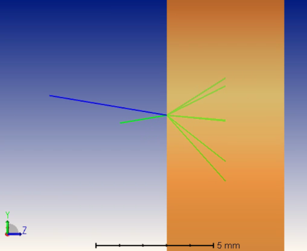
Let's simply open the attached cpp file and observe how it works in non-sequential mode.
This example is mainly modified from the built-in sample \Documents\Zemax\DLL\Diffractive\diff_samp_1.c
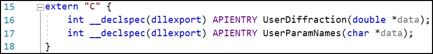
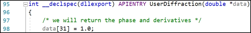
To compile the program as C++ code. We package the functions with extern 'C'.
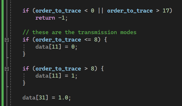
In this example, we only want to return diffraction ray direction and its relative intensity. So setting data[31] = 1 is enough. If we also know the polarization state or the full eletric field value, we can use data[31] = 2.
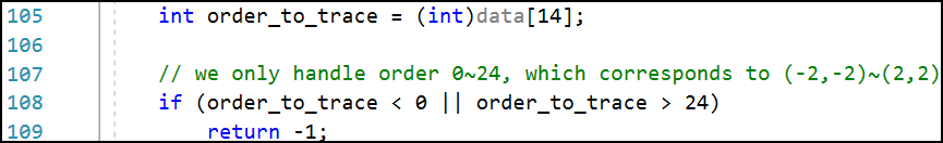
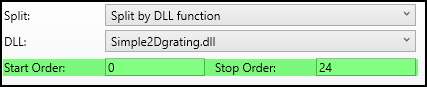
Here assumes we want to simulate 5 orders in x and y direction, so there should be totally 25 orders from (-5,-5) to (5,5). Because currently OpticStudio only considers the diffractive DLL simulates 1D grating, we need to represent the 2D orders in 1D. Here we will only consider orders from 0 to 24, which represents (-2,-2) to (2,2). If OpticStudio requests orders other than this range, we return -1, which will result in an geometric error in OpticStudio. For this reason, when using this DLL, the Start Order should be 0 and Stop Order should be 24 in OpticStudio.
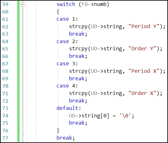
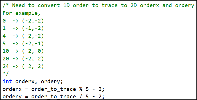
Then, we can decompose the 1D order into corresponding 2D orders.
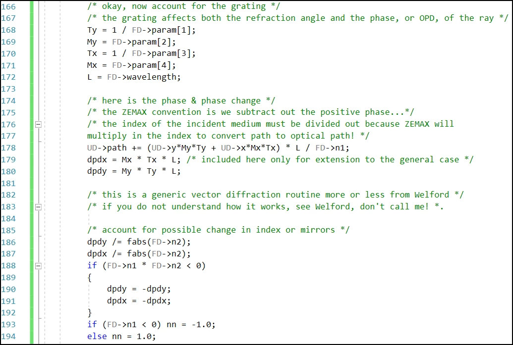
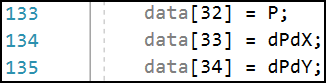
When data[31] = 1, we need to return the value for phase derivative and phase accumulation.
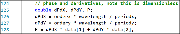
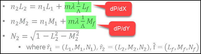
Note the phase derivative is same as what we described in page 3 in this forum post: How diffraction ray-tracing is calculated | Zemax Community
The phase (variable 'P') is simply accumulation of the phase assuming the phase at surfase vertex is zero.
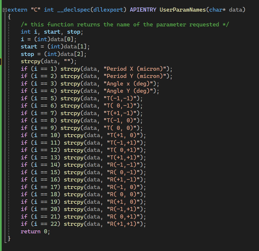
In UserParamNames(), we define the efficiency for each diffraction order.
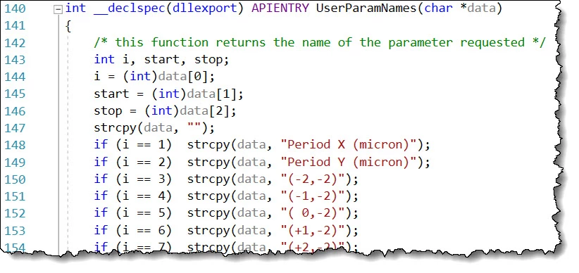
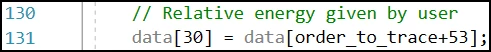
Then simply read it to data[30], which is the relative intensity reported to OpticStudio!