This forum post is a place to collect update history of diffractive tools beta functions, which includes all RCWA DLLs (and visualization API), polygon DLL, and Zemax Grating Data (ZGD) DLL.
Content:
1. Overview
2. Resources
3. Change history
Overview
Currently in OpticStudio, we are adding some useful DLLs to enhance the ability of fully simualting gratings. They allow OpticStudio to consider the efficiency when rays pass through diffractive optical elements (DOE), such like 1D/2D gratings, binary optics, or volume holograms. These extensions can be found in OpticStudio installations.
These tools improve frequently based on users’ feedback. We decide to provide functions with DLL so it can be updaetd fast upon users' request. Between each OpticStudio public releases, there might be several minor updates and bug fixes. This forum post is a place for changes history.
Note all tools provided here are only available with OpticStudio Premium Subscription. If users are interested in these functions, they can wait stable version until next the OpticStudio release. Or they can send an email to support inbox to request for latest beta DLLs.
Resources
- Simulating diffraction efficiency of surface-relief grating using the RCWA method
- Simulating diffraction efficiency of a volume holographic grating using Kogelnik's method
- How to simulate exit pupil expander (EPE) with diffractive optics for augmented reality (AR) system in OpticStudio: part 1 (part 2, part3)
- EMPossible
- Kogelnik, H., 'Coupled wave theory for thick hologram gratings, ' Bell Syst. Tech. J. 48, 2909-2947 (1969).
- Elias N. Glytsis and Thomas K. Gaylord, 'Rigorous 3-D coupled wave diffraction analysis of multiple superposed gratings in anisotropic media,' Appl. Opt. 28, 2401-2421 (1989)
- M. G. Moharam, Drew A. Pommet, Eric B. Grann, and T. K. Gaylord, 'Stable implementation of the rigorous coupled-wave analysis for surface-relief gratings: enhanced transmittance matrix approach,' J. Opt. Soc. Am. A 12, 1077-1086 (1995)
- Han-Hsiang Cheng and Xiaochaoran Tian 'An advanced ray-tracing model for multi-color holographic optical elements', Proc. SPIE 11188, Holography, Diffractive Optics, and Applications IX, 1118817 (18 November 2019); https://doi.org/10.1117/12.2537762
Change history
2023-08-07
- The maximum of parameter Max Order now supports up to 50. It’s limited mainly for fool-proof, but it’s realized to be too low.
- The DLL now allows more grating cache data in the memory. It was set low to avoid memory accumulation too high during optimization. However, it’s realized this can slow down the optimization when multi-wavelength is used as the cache can be deleted too often.
2023-07-04
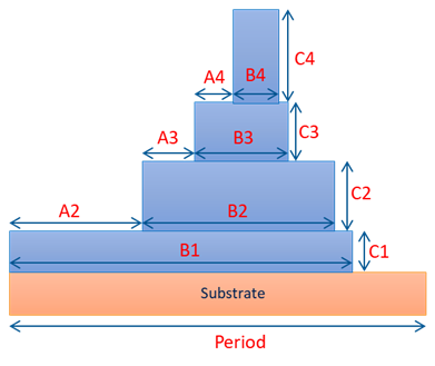
There is not update to the DLLs, but here we want to update explanations for srg_step2_RCWA.dll. The parameters in the geometry looks as following picutre. If the refractive index of any layer is set to zero, the refractive index will use what ever the background is, which is similar to you trun off the layer itself.
2022-12-21
The previous change to 2022-10-28 for srg_step2_RCWA.dll is not correctly implemented and is fixed now
2022-10-28
srg_step2_RCWA.dll has changed its rule. Before when setting parameters “Index Grate 2 (R)”, “Index Grate 3 (R)”, “Index Grate 4 (R)” to 0, it means the refractive index at these 3 layers are copied from layer 1. Now they will have the same refractive index as the substrate. This is same rule as the “Index Grate 1 (R)”.
2022-9-26 & 2022-9-30
Fixed an issue of loading dispersion file (coating_xx.dat) for RCWA 1D and 2D DLLs.
2022-9-13
Fix a bug that the parameter Grate Index 2~4 in the “srg_step2_RCWA220209.dll” are not considered correctly.
2022-5-13
There was a bug in Stochastic mode. When calculating power of each order, the power is wrongly calculated as Ex^2+Ey^2+Ex^2. This is fixed now.
2022-2-9
Fixed a bug in “srg_step2_RCWA220209.dll”. The bug behavior was that if you change a value for a parameter of the DLL, the change will actually be applied to the other parameter and the value of the original parameter that you want to change keeps same.2021-11-1
When using Stochastic mode, there was a bug where the diffracted ray’s power is larger than expected when metal is used in the grating. Note this is fixed.
Note from this version, the Stochastic mode 1 and 2 are deprecated and it’s always same as mode 3 in old version as long as this parameter is set as non-zero.
2021-11-1
When using Stochastic mode, there was a bug where the diffracted ray’s power is larger than expected when metal is used in the grating. Note this is fixed.
Note from this version, the Stochastic mode 1 and 2 are deprecated and it’s always same as mode 3 in old version as long as this parameter is set as non-zero.2021-08-25
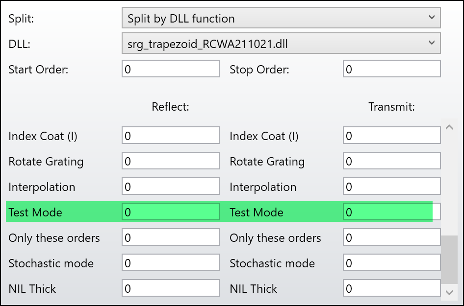
Now FFF is by default turned on. To turn it off, see the following explanations for the parameter “Test Mode”.
A new parameter “Test Mode” is added. By default, it should be zero, which means normal system. If it’s a positive value, some testing functions are triggered as below.
- Adding the value by 2^0 = 1: the DLL will report any coreerrors in a log text file.
- Adding the value by 2^1 = 2: the DLL will report more information mainly for debug.
- Adding the value by 2^2 = 4: the DLL will turn off Fourier Factorization Factor.
- Adding the value by 2^3 = 8: the DLL will turn on another algorithm T-Matrix. Note this is not yet ready at this timing with some bugs.
2021-08-25
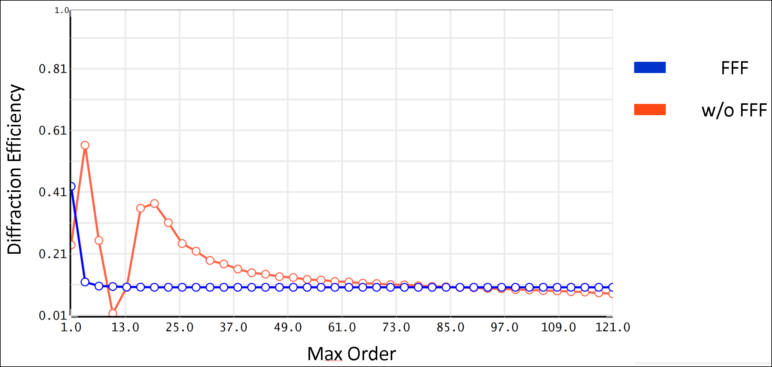
A benchmark has been done for FFF. The tested structure is from the following reference.
Convergence of the coupled-wave method for metallic lamellar diffraction gratings, Lifeng Li and Charles W. Haggans, Journal of the Optical Society of America A Vol. 10, Issue 6, pp. 1184-1189 (1993)
2021-08-23
Implement Fast Fourier Factorization to improve the convergence of metal material.
Some other minor stability improvements.
2021-07-14
The function of manual sizing of visualization tool window was broken and now is back.
2021-06-23
The efficiency plot in visualization tool doesn’t show correct data. Now it’s fixed.
2021-06-14
All DLLs are added with a new parameters “FFF”. When this parameter is set to non-zero, a method called “Fast Fourier Factorization” is used to calculate. Theoretically, this can make the convergence faster when there is a metal layer in the grating. In other words, less number is required for “Max Order” when metal material exists in the grating. This is still in experiment and should be used carefully.
2021-04-28
Tow bug fixes.
- In some cases, if the PC has more than 10 cores, the calculation speed would be very slow because all threads compete for getting shared resources. This is fixed now.
- When the given parameter period is negative, it means frequency in micron^-1. However, the period was wrongly multiplied by 1e6 times. This is fixed now.
Polygon grating DLL has been updated to include Scale X and Scale Y.
2021-04-20
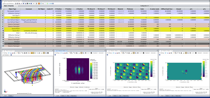
The DLLs didn’t consider the linear phase introduced by grating and now it’s fixed. This only affects if designers what to calculate Huygens PSF a shown below.
2021-04-07
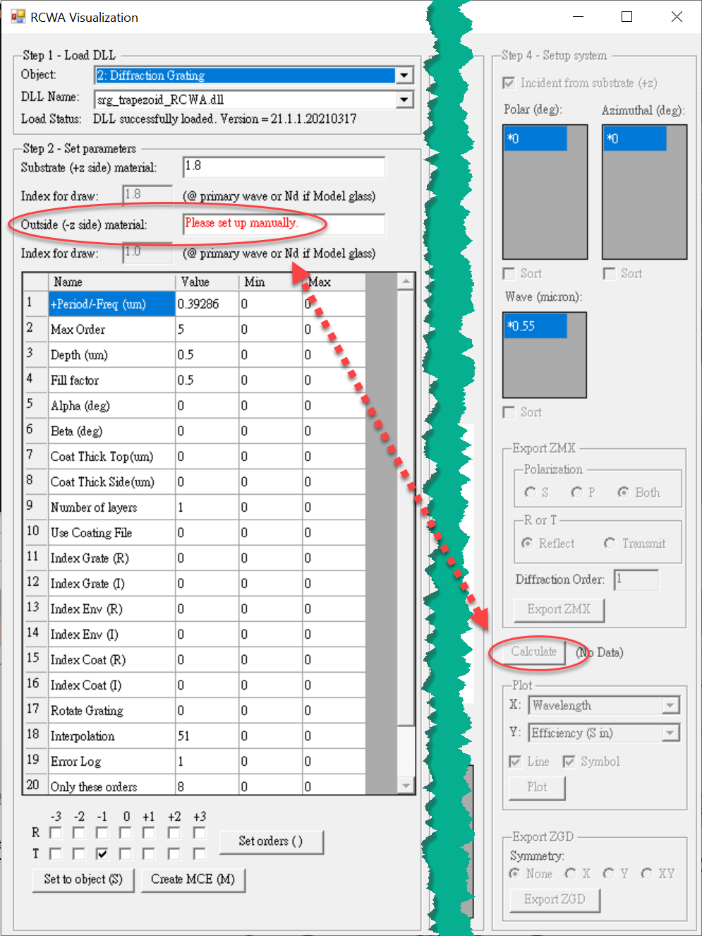
Now if Outside material is not specified, when click “Calculate” button, there will be an error message to warn the calculation would be wrong.
2021-04-05
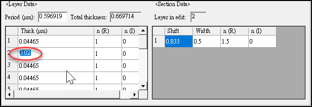
Fixed a bug that editing thickness and section data in layers & section table would fail.
2021-03-19
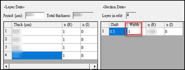
A bug is fixed in visualization tool. If a section in a layer has Width = 1, this section would not be drawn. Now it works correctly.
2021-03-17
Two bug fixes.
- When the input grating data for User defined DLL includes non-zero imaginary refractive index, the DLL stops work. Now it’s fixed.
- When using dispersion data (COAT_x.dat) to define grating material, if that includes non-zero imaginary refractive index, the DLL stops work. Now it’s fixed.
2021-02-19
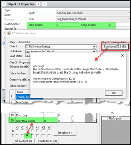
A checking code is added. If defined order filter includes orders that is outside of the range between Start Order and Stop Order Object Property, the DLL stops working. In visualization tool, there is an error message shows.
2021-02-02
Polygon grating DLL added a new parameter “Diffract back face”. When it’s set to non-zero, the grating will be on Face 2 instead of on Face 1.
2021-01-28
Polygon grating DLL now supports up to 30 points. The download link is included above
2021-01-24
Visualization tool has two slight changes in UI
- Now it’s possible to change DLL from UI. Note this will directly modify settings in OpticStudio.
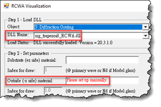
- Mark text to red if Outside material has never been changed manually. By default it’s 1.0 but it need users to correctly set up.
2021-01-22
Bug fix: all DLLs were wrongly set with an expire date after 2021-01-21. Now this is removed.
If you see the following error message when opening your design file. Please fix it with selecting new DLLs.
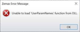
To make the design file work again, either one of the following methods would work.
Method 1
(1) Copy the beta DLLs, for example the srg_trapezoid_RCWA210122.dll, from zip file to \Documents\Zemax\DLL\Diffractive\
(2) Remove the old DLLs, which is srg_trapezoid_RCWA.dll in this case.
(3) Rename this DLL srg_trapezoid_RCWA210122.dll to srg_trapezoid_RCWA.dll.
(4) Now open the design file. And that should work.
Method 2
(1) Copy the beta DLLs, for example the srg_trapezoid_RCWA210122.dll, from zip file to \Documents\Zemax\DLL\Diffractive\
(2) Open your design file.
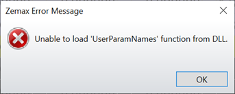
(3) You will see the following message. Click OK.
(4) Then go to your grating object > Diffraction Property. You should see as below. The DLL is wrong.
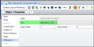
(5) Select the srg_trapezoid_RCWA210122.dll and the file should work again.
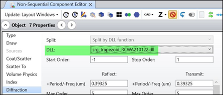
2021-01-13
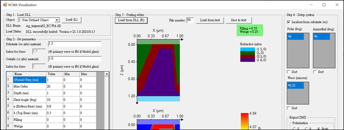
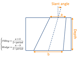
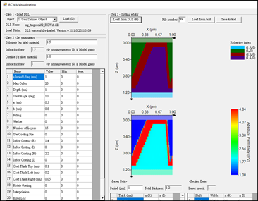
1. Visualization tool now calculated Filling and Wedge and shows the value if the DLL is trapezoid 2 and a or b is not zero. If both a and b are zero, a and b are calculated, using Filling and Wedge data and shows.
2. Polygon grating adding two parameters
--- “Scale”: all x and y points will be multiplied by this value to scale. If it’s zero, it’s converted to 1.0 internally.
--- “Z Center Mode”: If it’s 0, the local origin (0,0,0) is on the Face 1 as usual. If it’s 1, the local origin is shifted by -0.5*Thickness so it’s between the Face 1 and Face 2.
2021-01-12
Bug fix:
Wedge in trapezoid 2 is negative when b > a. Exchange a and b to make Wedge positive.
2021-01-11
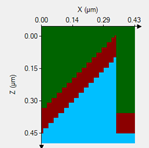
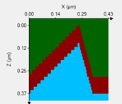
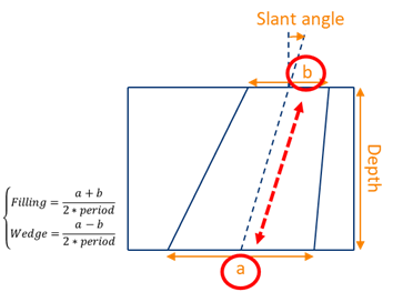
New grating shape (srg_trapezoid2_RCWA.DLL). The shape is defined as following picture. Note that:
- If parameters Filling or Wedge are non-zero, then a and b are ignored. Otherwise, a and b are used for the shape definition.
- Coating thickness in this DLL can be separately defined for top, left side, and right side.
- The speed of interpolation mode is improved by about 15%~20%.
2021-01-06
Visualization tool
1. Incident angle is now defined by polar and azimuthal angles (theta and phi). This matches the convention more in both academic and industry.
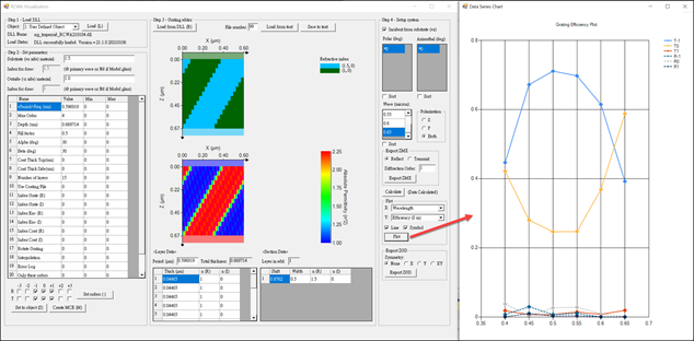
2. Add a button to calculate efficiency data. The data is saved in RAM and can be plotted by “Plot” button or exported by “Export ZGD” button.
3. Add a button to plot efficiency data.
--- There 3 dimensions, wavelength, polar angle, azimuthal angle, but we need to choose one of them as the X-axis.
--- For the rest dimensions, the data is calculated for those cells with a “*” mark. The “*” mark can be set to other cell by selecting the cell and press Ctrl + Z.
4. Add a button to export Zemax Grating Data (ZGD) file. More information about ZGD can be found by the download link above.
5. Note new DLLs are required in order to use new functions in the visualization tool.
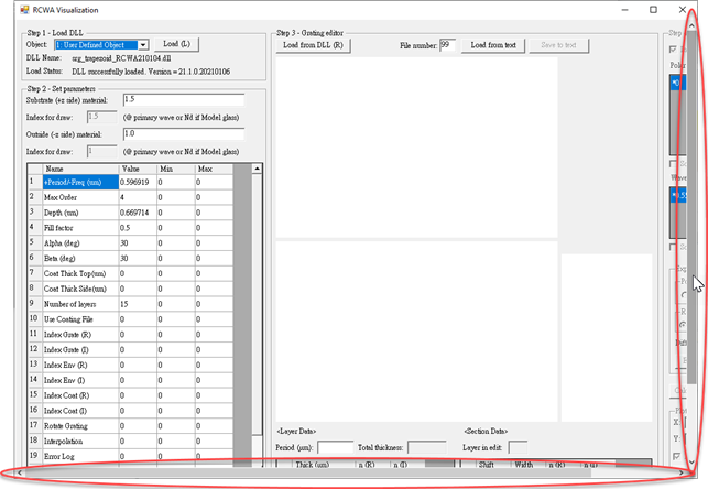
6. Now if the window is resized by user, a scroll bar will appear when needed. This helps users who use notebook.
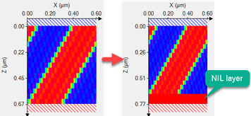
7. Now the following DLLs support NIL layer: srg_blaze_RCWA, srg_gridwirepolarizer_RCWA, srg_step_RCWA, srg_trapezoid_RCWA. The thickness of this layer can be set by new parameter “NIL sub thick”.
8. The number of output rays when Stochastic mode is used is now fixed to only 1 and is regardless to the value in Start/Stop Order settings in the UI. This makes the settings easier and less confusing. If multiple output rays are desired, please send feedback to support team.
9. Speed of interpolation mode is improved by 15%.
10. A new DLL is created for reading pre-calculated efficiency data for 1D/2D gratings. Lumerical data input is also supported. Check the document in the download link for more information.

2020-12-17
A new User Defined Object DLL is created for polygon grating.
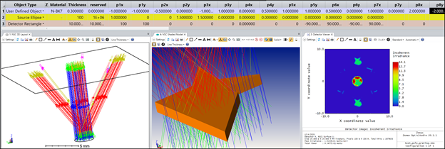
2020-12-04
Now the DLL compile date can be checked in the visualization tool. Note this will only work with newer DLLs.

2020-11-06
Add a new parameter “Coat mode” for us_blaze_RCWA.dll. When it’s set to “1”, the grating now can be shaped as below.

