Ideal Lens DLL (user-defined sequential surface satisfying the Abbe sine law)
NOTE (added 2/5/2024): A new version of the DLL is now available, so I have deleted the older one supplied with the posting below. Please see this link for latest version:
Attached is a user-defined surface DLL that functions as an ideal thin lens obeying the Abbe sine condition. It is distinctly different than a paraxial lens surface and is particularly well-suited for simulation of high-NA objectives. The Ideal Lens surface requires two user-supplied parameters, namely the effective focal length and the paraxial magnification at which the lens yields optimal performance. It supports arbitrary conjugates (i.e., finite conjugate, or infinite conjugate in either object or image space) and is designed to work in both standard space and mirror space. A detailed description is provided in the included summary document, along with a discussion of several examples. The source code is not provided for now, but any and all feedback regarding the DLL functionality would be appreciated. Changes can be made accordingly.
Here is a related link:
Regards,
Jeff
Page 1 / 1
Hi Jeff,
Thanks for sharing your work, it looks super interesting. I’ll try it as soon as I can :)
Out of curiousity, have you read the paper from Hwang and Lee regarding the immersion lens model? I’m curious to hear your thoughts about the matter. I couldn’t reproduce some of their figures, particularly Figure 8, I had a much greater error than what was reported.
Take care,
David
Hi David,
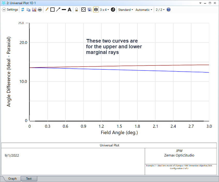
Yes, I’ve taken a look at the Hwang paper. It’s okay, but not the most clear paper I’ve ever read. They appear to use a patented objective design as their baseline against which to compare a standard paraxial lens model versus a model developed in the paper. Fig. 8 claims to provide comparison results based on marginal ray data. The thin paraxial lens model of Sec. 3.1 looks like it only applies to a lens in air, while their custom model simulates an immersion objective. I haven’t tried to generate the patented objective model, but I can easily compare a paraxial lens to my ideal lens model. To get results even close to what are shown in Fig. 8, I keep the EPD value fixed, but then have to compare a paraxial lens in air to an ideal lens with an immersion index of 1.5 (which is an apples vs. oranges comparison as they have different working distances). In any event, when doing so, this is what I find:
It’s not exactly the same, but it’s in the ballpark. It would be much better if they provided absolute results in some of the graphs instead of only differences.
Overall, I would suggest filtering the results of this paper with your own experience and judgment.
Regards,
Jeff
Hi Jeff,
Thank you for your reply. I was quite enthusiastic at first when I came across this paper. I need to learn to temper my expectations. I feel better knowing it isn’t just me though.
Looking forward to try your Surface!
Take care,
David
Hello @Jeff.Wilde,
Thank you for sharing this ideal lens DLL and excellent documentation.
One simple benefit is that it allows allows simulation of pure distortion. I’ve often wanted create a perfect image of distortion for various reasons and never found a way to do this with the default OS tools.
Thanks again!
Thanks for the feedback John! Glad you find the ideal lens surface useful.
Regards,
Jeff
Hello Jeff,
Thanks for the DLL, that's very useful.
I'm trying to model a system of two opposed microscope objective lens (see attachment). But zemax freezes when I try to display the zernike standard coefficients with the OPD mode of the last paraxial lens set to 1. It works fine if I replace the second objective lens (the infinite rear conjugate one) with a paraxial lens but it also crashes if I replace the first objective lens (the infinite front conjugate one) with a paraxial lens. So the culprit is apparently the infinite rear conjugate one.
Is this expected ? Maybe my version of Zeemax is too old (October 26, 2010).
Regards,
Marie
Hi Marie,
Please use OPD Mode = 0 with paraxial lenses. I’ve seen the same problem with mode 1, but it’s not consistent -- sometimes it causes OpticStudio to hang, while in other cases (i.e., different model layouts) it doesn’t. I’m not sure exactly what is going on, and it’s difficult to debug because I don’t know exactly how mode 1 is coded.
However, when I have some time, I may look into this problem a bit more, but Mode = 0 should work okay.
Regards,
Jeff
Ok, thanks
Regards,
Marie
Thank you for this very helpful surface. So the dummy surface above the user defined lens surface specifies the material in object space. Will this work correctly if another material is placed in the object space? For instance in the case of a high NA water immersion objective (index 1.33) one might put a cover slip of index 1.5 into that space right before the object principal plane
Yes, the index of the material physically in contact with the lens should be given by the dummy surface (0 thickness) as well as the surface prior to the dummy (with some non-zero thickness). Prior to that, you can use whatever surface materials and thicknesses you like.
Would still love to see this built into OS, it’s a great contribution.
Add my vote for making the Cardinal Lens a built-in surface. It's a must for microscopists.