Dear OpticStudio users,
In the context of my research at the MRC - Laboratory of Molecular Biology, I am tolerencing a custom light-sheet microscope, which uses commercial immersion objective lenses.
When tolerancing an optical system, which uses non-immersion objective lenses, I would often assume that this element can be replaced with a paraxial lens in a first approximation. However, when it comes to immersion objective lenses, this assumption breaks Abbe's sine condition [1]. Consequently, it is usually not possible to satisfy the specifications, namely focal length, back-aperture diameter, and numerical aperture, of an immersion objective lens with a single paraxial lens.
A direct solution to this problem involves patent search, and cumbersome reverse engineering to try and get your hands on the actual design of the commercial immersion objective lens. However, this is time-consuming, and requires a different kind of expertise.
To address this issue, Hwang and Lee published an immersion objective lens model [1] in 2008. This model uses a single spherical surface with a modified refraction law to reconcile Abbe's sine condition.
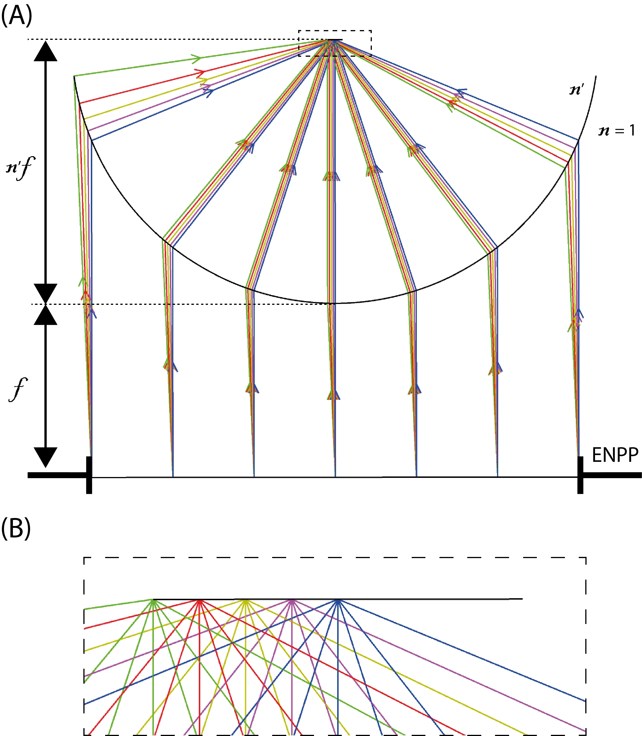
I have created a DLL, and a sample file (attached to this thread), that reproduce the model of Hwang and Lee (see Fig. 1).

Figure 1 (A) Reproduction of Fig. 3 in [1] using the DLL in OS. n' is the immersion medium refractive index, and f is the objective lens focal length. (B) Zoom of (A) at the sample plane showing how the different fields focus to a single point. ENPP: entrance pupil position.
Unfortunnately, I haven't been able to reproduce Hwang and Lee's results yet, but I think it is related to my implementation of the real immersion objective lens that is used for comparison (Fig. 6 in US patent US7199938 I believe). I am willing to discuss this issue with whoever is interested, and I will update this thread accordingly. In this regard, one might want to know that there could be a mistake in US patent US7199938 in page 16 around line 50. The r6 radius of the imaging lens should be positive I think (as seen in Fig. 17 of the patent).
Please also note that Eq. 5 of the paper is an approximation when the angle phi is zero. The complete formula involves solving a quadratic equation. Consequently, it also changes the form of Eq. 6, but luckily the norm of the correction vector corresponds to the path t in OpticStudio standard DLLs.
[1] S.-U. Hwang and Y.-G. Lee, Opt. Express 16, 21170 (2008).
Installation: If you load the archive attached in OS, it should also place a copy of the DLL in your document folder.
Parameters: the parameters of the DLL are the immersion medium refarctive index, and the focal length of the objective lens.
Let me know if you find this useful or if you want to try to reproduce the paper's results.
Kind regards,
David


