It is common for illumination design to have complex shapes which are difficult to describe by a mathematical formula. For example, custom collimators, waveguides, reflectors, and so on could be represented by freeform curves. When such optical components are designed in a CAD program, we can't optimize their shape in Zemax after importing CAD files.
To overcome this issue, I provide an example of how to convert CAD data of a TIR lens into a parametric surface and optimize it for light collimation.
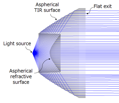
In this example I’m using TIR lens. It consists of TIR surface and refractive surface, as shown below.
Reference: Pencil of Rays
First, we will fit TIR surface.
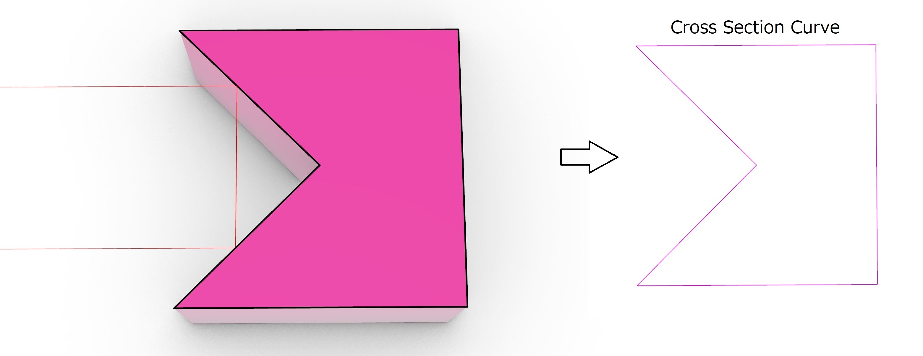
Zemax has a Freeform Z object, which is formed by drawing a cubic spline curve through a series of points in the YZ plane:

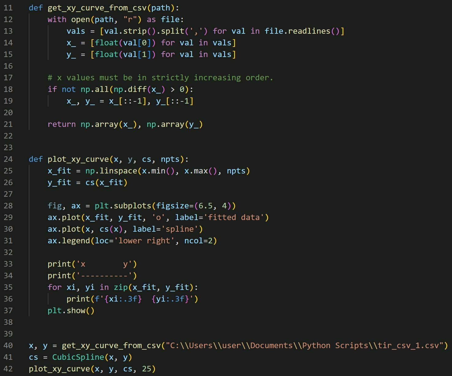
Our target is to retrieve these YZ pairs from a solid model cross-section via cubic spline interpolation. Spline interpolation can be done in python using scipy.interpolate.CubicSpline(Z,Y):
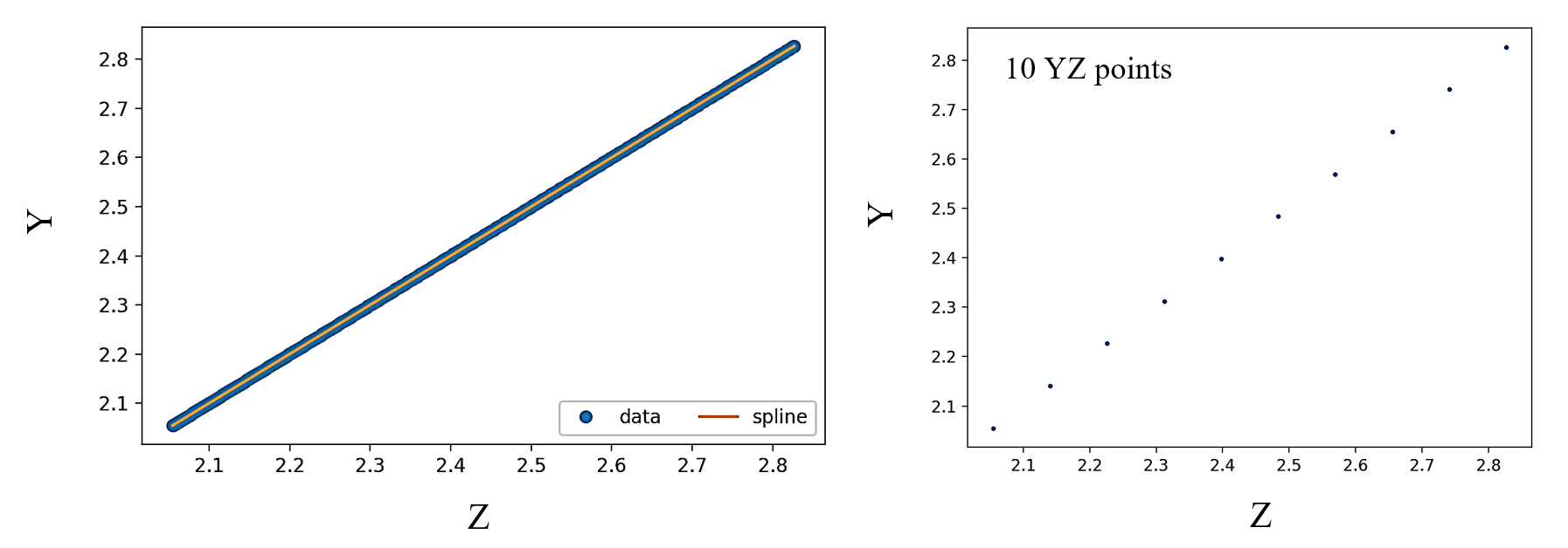
After interpolation, we choose the number of points for Freeform Z. I found it is sufficient to set this value between 10 to 20 points based on the curvature complexity.
Second, I use aspherical surface to fit a refractive part of TIR lens.

Next, we can get a complete parametric representation of TIR lens by Freeform Z and Aspherical lens:
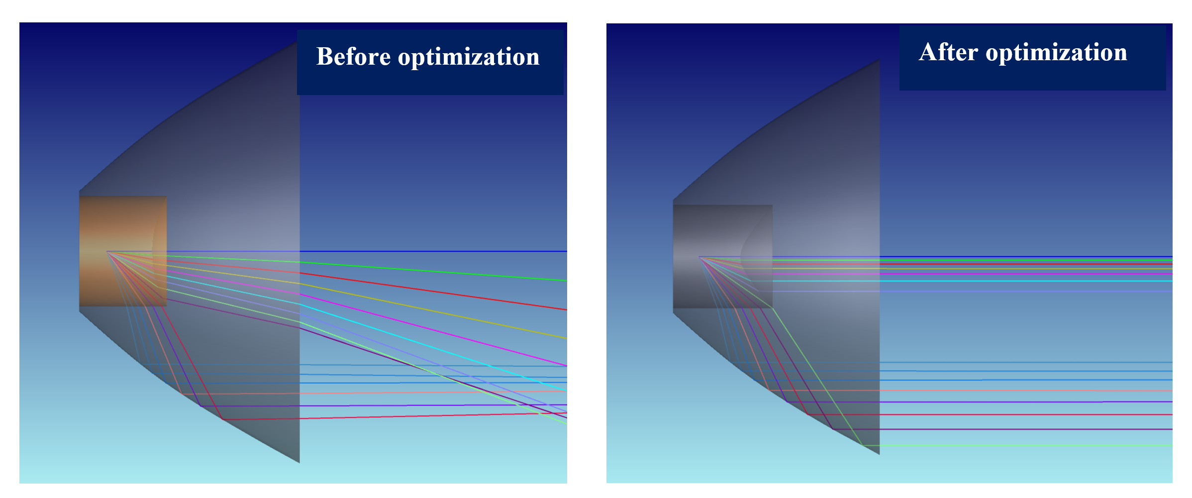
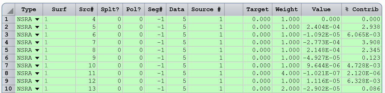
Finally, to optimize TIR lens for light collimation, I use NSRA operands targeting Y-cosine to be zero:
This method can be applied to any CAD data with rotational symmetry. For non-symmetrical lenses, we can apply similar approach by using Grid Sag.
Regards,
Mykyta