API (Python and MATLAB Interactive Extension) Calculate the Ray Transfer (ABCD) Matrix for thick Lens

  • 11 January 2022
  • 9 replies
  • 1809 views

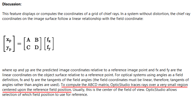
To compute the ABCD matrix, OpticStudio traces rays over a very small region centered upon the reference field position. Usually, this is the center of the field of view. OpticStudio allows selection of which field position to use for reference.By default, OpticStudio sets the corner of the field grid in object space to be at the maximum radial field distance. Because object height is linear with the tangent of the field angle, the full width of the field when angles are used to define the field is given by

Where θr is the maximum radial field angle at the corner of the field.

The ray coordinates in image space for the very small field of view are used to determine the ABCD matrix components. The use of an ABCD matrix allows for coordinate rotations. If the image surface is rotated, such that a y object coordinate images to both an x and a y image coordinate, the ABCD matrix will automatically account for the rotation. The grid distortion plot shows the linear grid, and then marks the actual chief ray intercept for a ray with the same linear field coordinates with an "X" for each point on the grid.

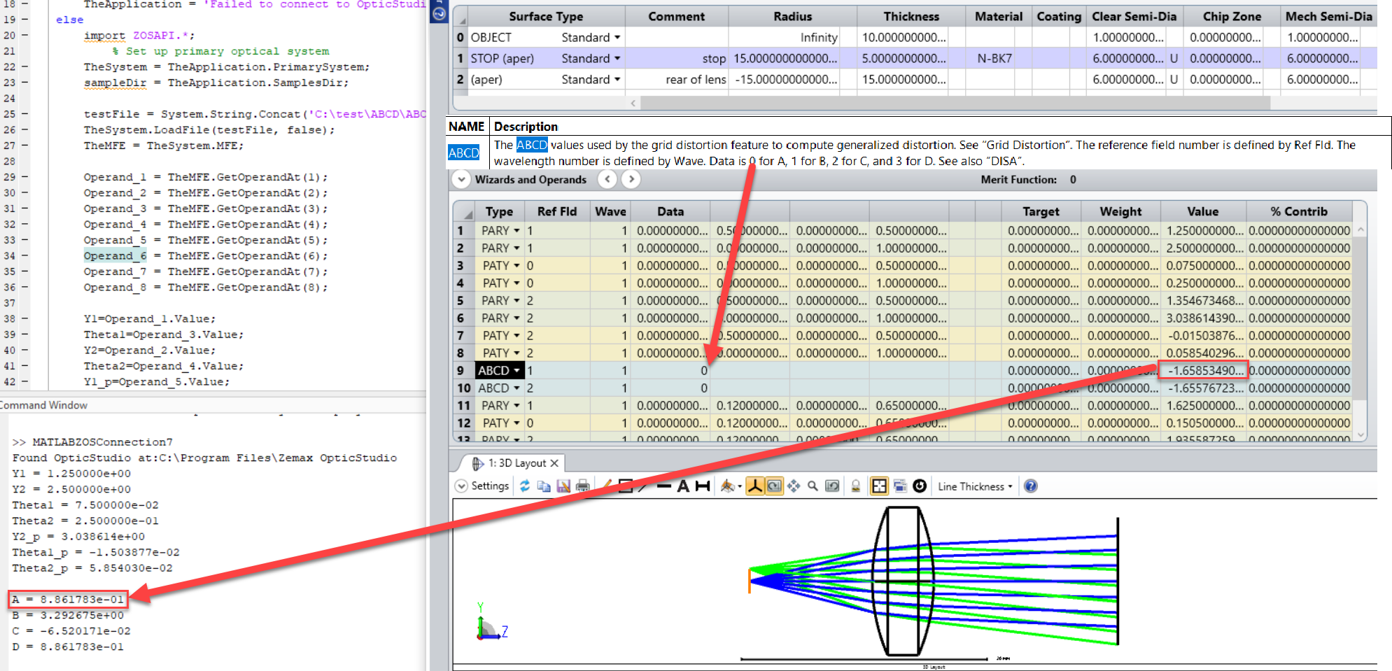
In OpticStudio, we can calculate the Ray transfer (ABCD) matrix using ZOS API(MATLAB and Python Interactive Extension). My colleague has an idea of doing using operands .We can calculate ray transfer matrix element by knowing Height of incidenct ray,Height of refracted ray ,angle of incidence and angle of refraction .As we have PARY or PAXY operands for showing the height of Ray in X or Y -coordinate respectively  and PATY  shows tangent of the angle the paraxial ray makes in the Y-Z plane after refraction .As shown in image1 below.
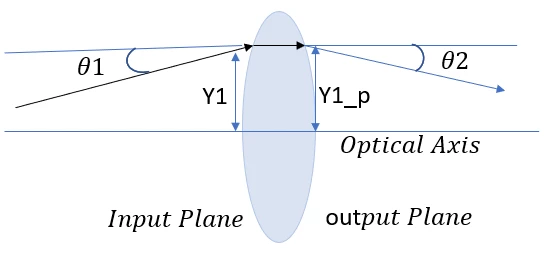
In ray transfer (ABCD) matrix analysis, an optical element a thick lens gives a transformation between (Y1,theta1) at the input plane and (Y1_p,theta1_p) when the ray arrives at the output plane.


We can export angle of incidence and angle of refraction using PATY Operand and Height of incidenct ray and Height of refracted ray using PARY inYZ Plane to a variable in Matlab .Using these values to calculate A,B,C and D Values for Ray Transfer Matrix . In this Image 2, we can see the ABCD Matrix value in Matlab output console uisng MATLAB-API Interactive extension.
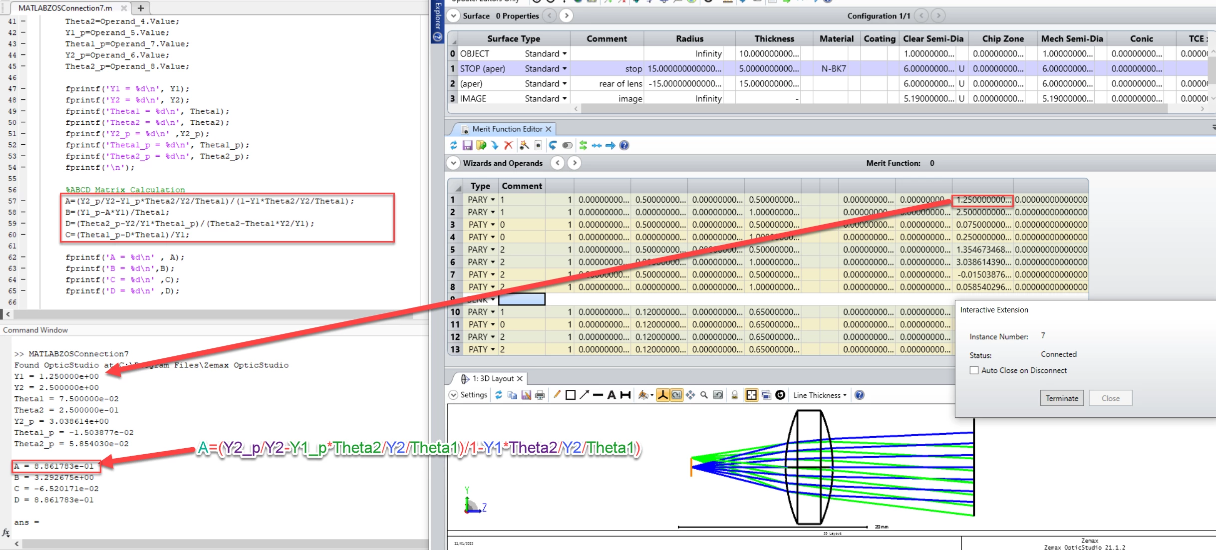
Image 2

Similar in Python we can obtain value for ABCD Matrix shown in Image 3.
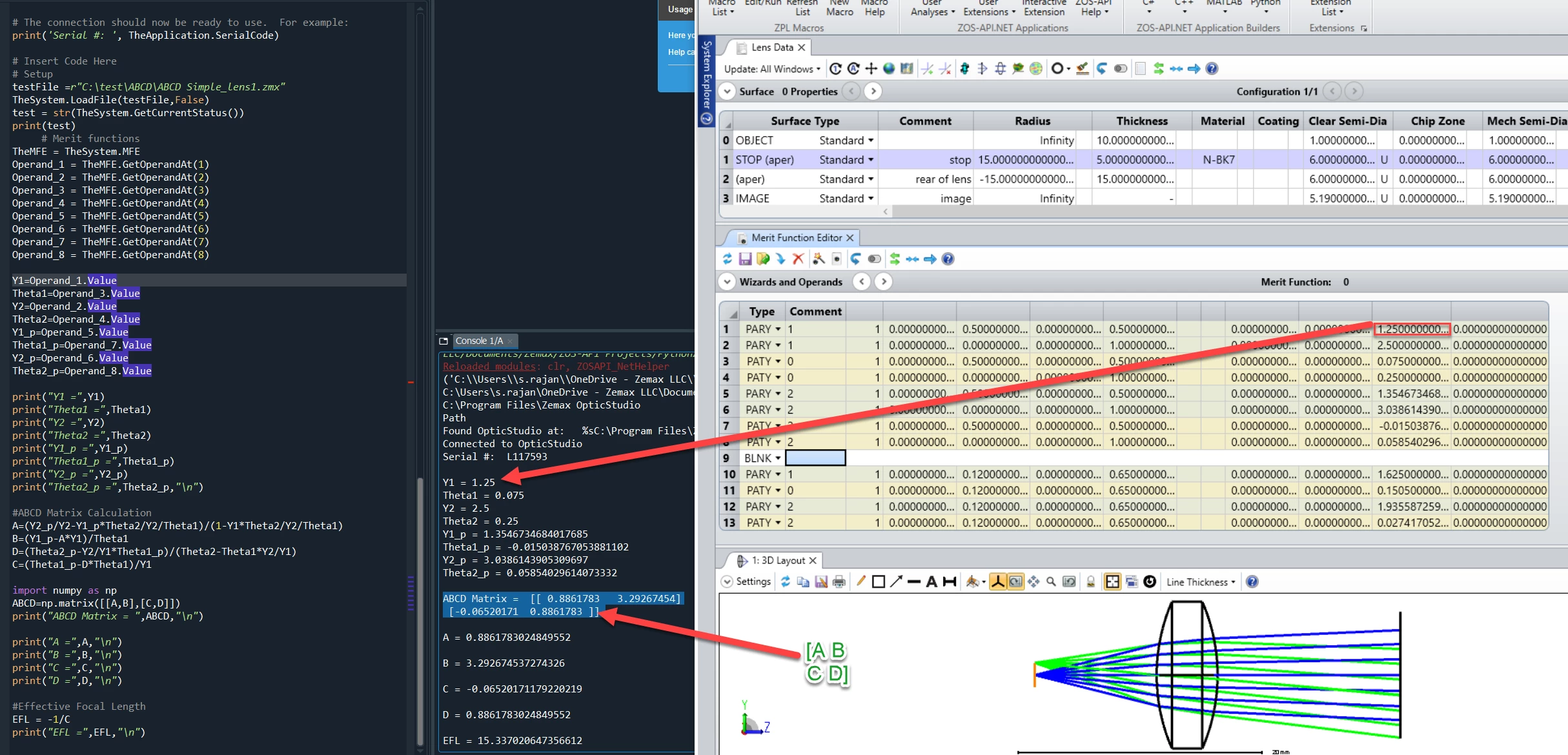
Image 3

Click here to download

9 replies

Userlevel 7
Badge +3

Hi Sahil,

Forgive me if this is obvious, but the ABCD matrix is returned in the System Data and Prescription Reports, and by the, er, ABCD optimization operand. Why are you going to all this trouble to return it via ZOS-API, Python and Matlab?

  • Mark
Userlevel 4
Badge +1

Hello Mark,

Thanks Mark for bringing this query in this post . The ABCD matrix generated in the System/Prescription Data is actually a mapping of the object to image coordinates . So, this is really a calculation for distortion and not a ray transfer matrix calculation. 

As we can see in the Image the Value of A calculated by ABCD operand doesn’t match to Value A calculated by the equation in Program. ABCD Operand values are not been calculated for any surface but these values are used by Grid Distortion.

Regards

Sahil

Userlevel 7
Badge +3

Erm...not really.  ABCD simply maps what’s on the object side to what’s on the Image side of whatever range of surfaces you want to describe. I cannot see what the distinction is that you are making between ‘ray mapping’ and ‘distortion’. These are exactly the same thing in the context of the ABCD approach

Another way of thinking about this is that distortion is only an ‘aberration’ because it disagrees with aberration theory :grinning:. Aberration theory predicts a ray’s location incorrectly, and for some reason lost to history we consider the real ray location to be ‘aberrated’ with respect to the theory. ABCDs should only ever work with real ray data: measured (real) position and angle on the left and measured position and angle of the right. What’s lost is the optical path length added or subtracted, which is why ABCD surfaces are not useful for imaging purposes

Your code should produce the same results as OS if you set it to model the whole system though, that’s a basic sanity check of your algorithm. 

Userlevel 7
Badge +3

Hi Mark,

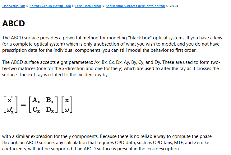
Aren’t we talking about two different ABCD matrices?  The ABCD *surface* is a traditional first-order “black-box” description of ray propagation between input/output planes for a lens or, more generally, an arbitrary set of optical components.  However, OpticStudio also generates what looks to be a completely different ABCD matrix for use with grid distortion:

This second version is the one that has its component values returned by the ABCD merit function operand as well as in the System Data report.  Not sure why the “ABCD” nomenclature was used for the distortion analysis; it clearly seems like a potential source of confusion.  Am I missing something here?

-Jeff

Userlevel 7
Badge +3

Ooohh, sorry Jeff and Sahil, I think you are right!

Both use a linear transformation, but one maps radial position and angle, and the other x and y. Ultimately you can resolve one in terms of the other but they are different things. Sorry Sahil I get it now!

  • Mark
Userlevel 7
Badge +3

I think the terminology is definitely confusing.  An ABCD matrix is well-known in optics.  The fact that OpticStudio also uses exactly the same nomenclature for a different linear transformation is unfortunate, but I guess at this point it’s already baked into the cake...

Userlevel 4
Badge +1

Hello Mark and Jeff ,

It’s fine Mark .Actually terminolgy is confusing . We have couple of customer requests regarding Ray Transfer(ABCD) Matrix and newly joined optical engineers like me get confused with it, so I tried to post it in Forum .I hope this post will help .

Thanks

Sahil

Userlevel 1

Hello Sahil,

very interesting topic. However the download libk seems to not working for me.

Is it possible to re-upload?

Userlevel 6
Badge +2

Hi @dgeorgiev! Apologies I hadn’t seen your post. I have updated the download link.

Reply