Hi Everyone,

I would like to ask how to use zbftilt? The help document reads a bit confusing: 

This keyword requires the name of the ZBF file and four numbers. The phase of the beam is modified by a phase angle given by θ = ( x – cx )tx + ( y – cy )ty . The cx and cy values are the center of the phase tilt, and tx and ty are the slopes of the tilt in units of radians per lens unit length. The coordinates x and y refer to positions within the beam file, with the center coordinate (x = 0, y = 0) being at the point (nx/2 + 1, ny/2 + 1) where nx and ny are the number of points in the x and y directions. The length units in the ZBF file are converted automatically to the current lens units. The resulting data is written back to the same file name.


If I want to rotate an elliptical beam mode by 90°, how should I write it?

Thanks!

Di

I feel this command is used in manipulating the phase of beam mode.

Is there a way to simply exchange x and y so that I can have a horizontally elliptical beam to be a vertically elliptical beam?

Thanks,

Di


@bgdi10262 


Not sure it is the most straightforward solution but there might be a programmatic approach to this problem.

@Michael Cheng shared some codes to read binary files, such as ZBF:

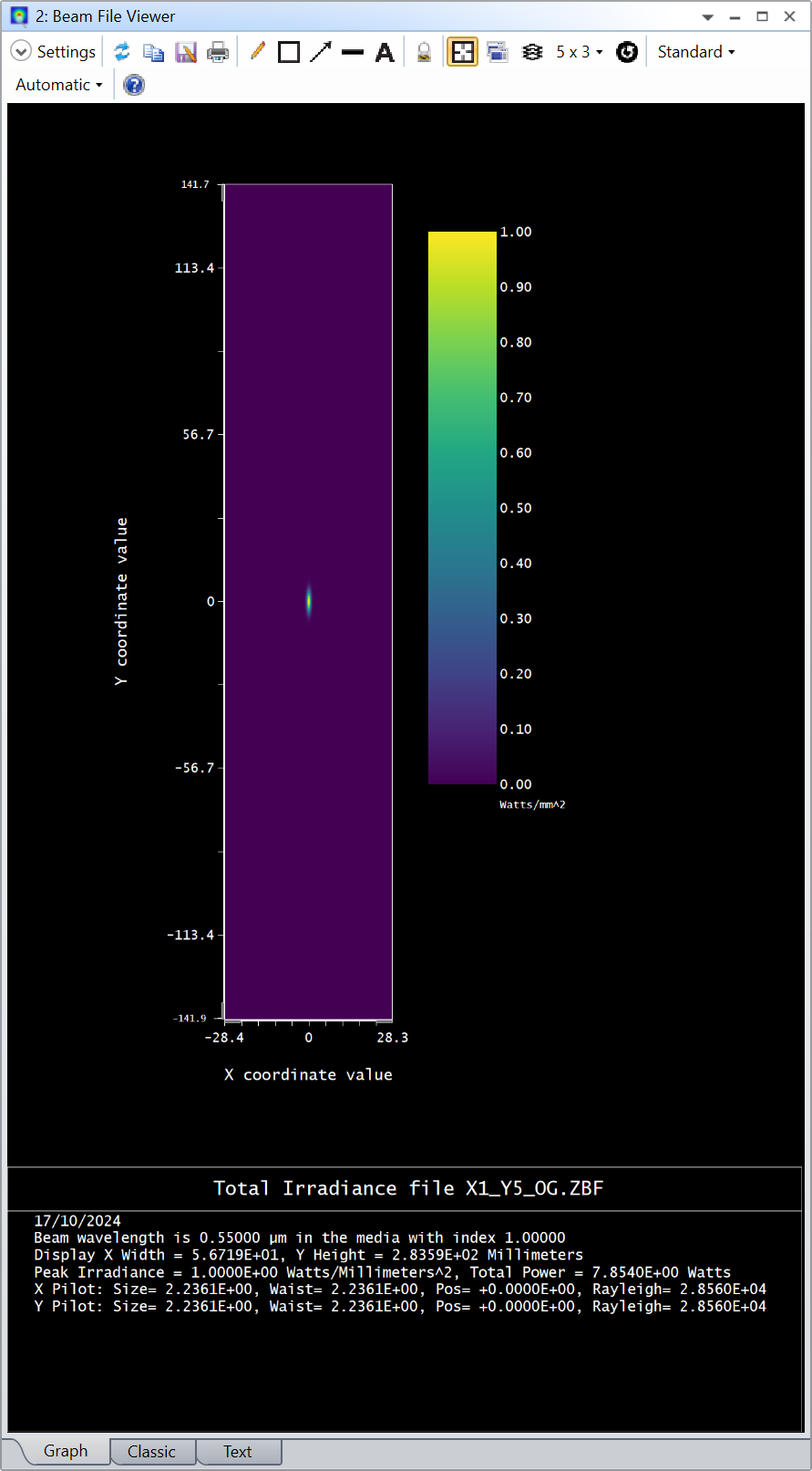
I made a “vertical” beam (attached to my reply):

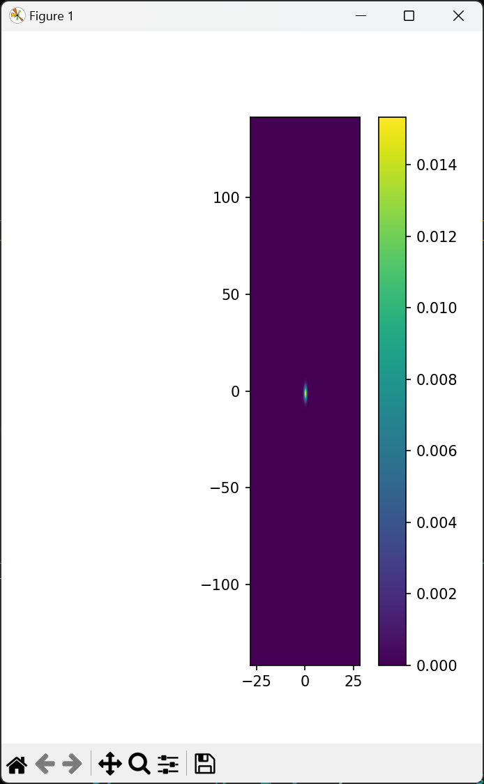
And tried to plot it in Python:

import matplotlib.pyplot as plt
import numpy as np
import struct

filepath=r'C:\Users\davnguyen\Documents\Zemax\POP\BEAMFILES\X1_Y5_OG.ZBF'

with open(filepath, 'rb') as bfile:
Version = int.from_bytes(bfile.read(4), byteorder='little')
Nx = int.from_bytes(bfile.read(4), byteorder='little')
Ny = int.from_bytes(bfile.read(4), byteorder='little')
IsPol = int.from_bytes(bfile.read(4), byteorder='little')
Units = int.from_bytes(bfile.read(4), byteorder='little')
Unused = int.from_bytes(bfile.read(16), byteorder='little')
Xspacing = struct.unpack('d', bfile.read(8))e0]
Yspacing = struct.unpack('d', bfile.read(8))e0]
X_ZPos = struct.unpack('d', bfile.read(8))e0]
X_ZR = struct.unpack('d', bfile.read(8))e0]
X_W0 = struct.unpack('d', bfile.read(8))e0]
Y_ZPos = struct.unpack('d', bfile.read(8))e0]
Y_ZR = struct.unpack('d', bfile.read(8))e0]
Y_W0 = struct.unpack('d', bfile.read(8))e0]
Wave = struct.unpack('d', bfile.read(8))e0]
Indx = struct.unpack('d', bfile.read(8))e0]
Rec_Eff = struct.unpack('d', bfile.read(8))e0]
Sys_Eff = struct.unpack('d', bfile.read(8))e0]

Ex = np.zeros((Nx, Ny), dtype=complex)
Ey = np.zeros((Nx, Ny), dtype=complex)

for xx in range(Nx):
for yy in range(Ny):
Ex xx, yy] = struct.unpack('d', bfile.read(8))e0] + 1j*struct.unpack('d', bfile.read(8))e0]

I = np.abs(np.transpose(Ex))**2

plt.figure()
plt.imshow(I, cmap='viridis', extent=e-Nx/2*Xspacing, Nx/2*Xspacing, -Ny/2*Yspacing, Ny/2*Yspacing])
plt.colorbar()
plt.show()

The problem is that the spacing is not uniform in X and Y. You find the spacing in the variables Xspacing and Yspacing. Therefore, before applying a rotation, I believe the sampling should be made uniform first (same spacing in X and Y). Then, you could rotate the beam and write a new ZBF file (I didn’t have time to try, but perhaps this can still be helpful).

Take care,


David


Hi Di,

if you are searching for another, not programmatic approach to rotate a beam, I suggest adding Coordinate Breaks to wrap around all components enclosed between the surface where you launch the POP beam and the Image surface using the Tilt/Decenter Elements Tool button located at the top tool bar. Therefore, please define 90 degree rotation around Z axis to rotate beam from horizontal to vertical orientation.

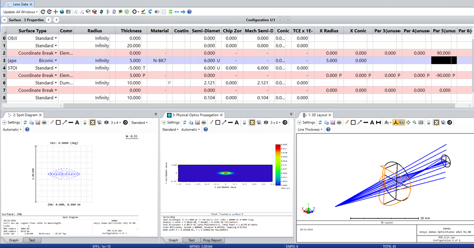
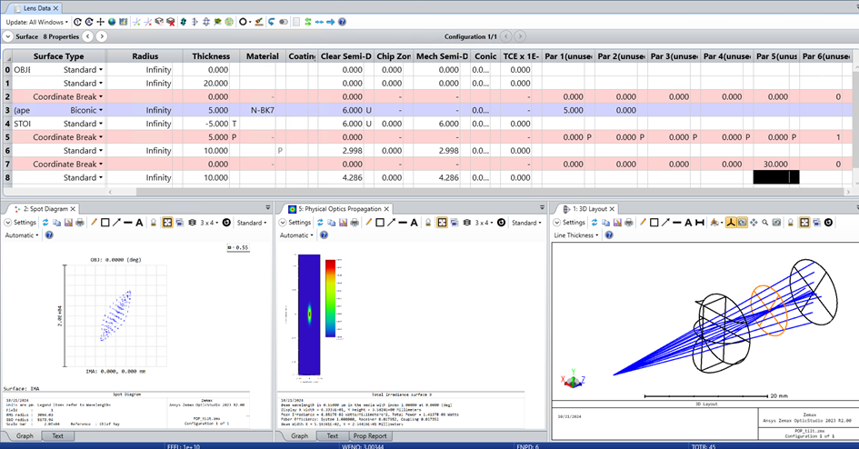
What I have done, is to first define an elliptical vertical beam, generated through a biconic lens.

Afterwards, I have defined 2 Coordinate Breaks around this system (surface 2 & 5) as described above.

As you can see, the orientation on image plane is now shown 90 degree rotated in POP and Spot Diagram. With varying the value for Tilt About Z, your elliptical beam rotate accordingly.

Whereas, when you are inserting another ‘dummy’ Coordinate Break (surface 7) right before the image plane (rotating the image plane only), you can see, that this is affecting the Spot diagram, but not the POP feature. Therefore, please keep in mind, that POP feature displays the results on a plane tangent to the Chief Ray, and on local coordinates. 

Best Regards,

Sabrina


Hi All, thank you so much for the profession help. We ended up writing python program to rotate the POP.


@bgdi10262 any chance you can share your implementation here? It might be useful for other people in the community. Thanks and take care,


David


Hi Di,

if you are searching for another, not programmatic approach to rotate a beam, I suggest adding Coordinate Breaks to wrap around all components enclosed between the surface where you launch the POP beam and the Image surface using the Tilt/Decenter Elements Tool button located at the top tool bar. Therefore, please define 90 degree rotation around Z axis to rotate beam from horizontal to vertical orientation.

What I have done, is to first define an elliptical vertical beam, generated through a biconic lens.

Afterwards, I have defined 2 Coordinate Breaks around this system (surface 2 & 5) as described above.

As you can see, the orientation on image plane is now shown 90 degree rotated in POP and Spot Diagram. With varying the value for Tilt About Z, your elliptical beam rotate accordingly.

Whereas, when you are inserting another ‘dummy’ Coordinate Break (surface 7) right before the image plane (rotating the image plane only), you can see, that this is affecting the Spot diagram, but not the POP feature. Therefore, please keep in mind, that POP feature displays the results on a plane tangent to the Chief Ray, and on local coordinates. 

Best Regards,

Sabrina

You need to be very careful about enclosing the Stop surface inside a Coordinate Break pair if you’re using Ray Aiming.  The RA algorithm assumes the Object Plane and the Stop surface are not rotated so this can easily fail for complex systems.


Reply