Solved

Mixed-mode ray-tracing through tilted STEP file window with optical system behind it for use of STAR module

  • 19 January 2023
  • 2 replies
  • 141 views

Userlevel 1
Badge

I am almost out of my mind here!

I have multiple tilted windows (STEP files) that I have to place in front of an optic and ray-trace through the entire system.  Once I get those set up, I have to apply thermal and stress data to those windows via the STAR module and analyze impacts.

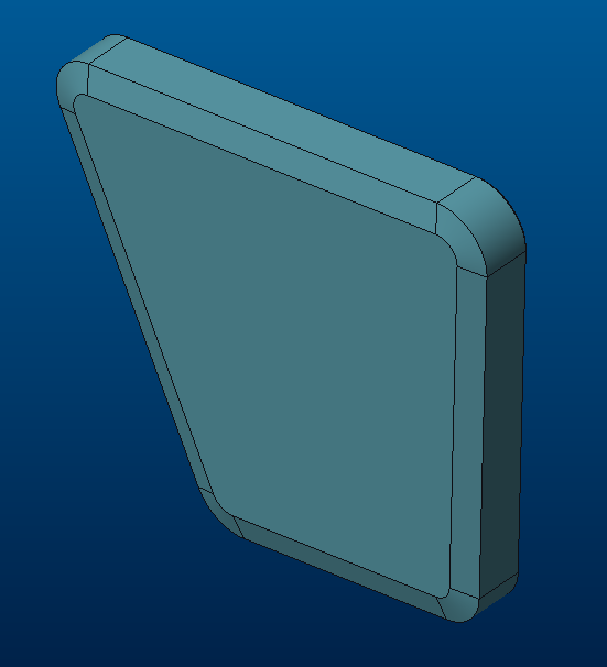
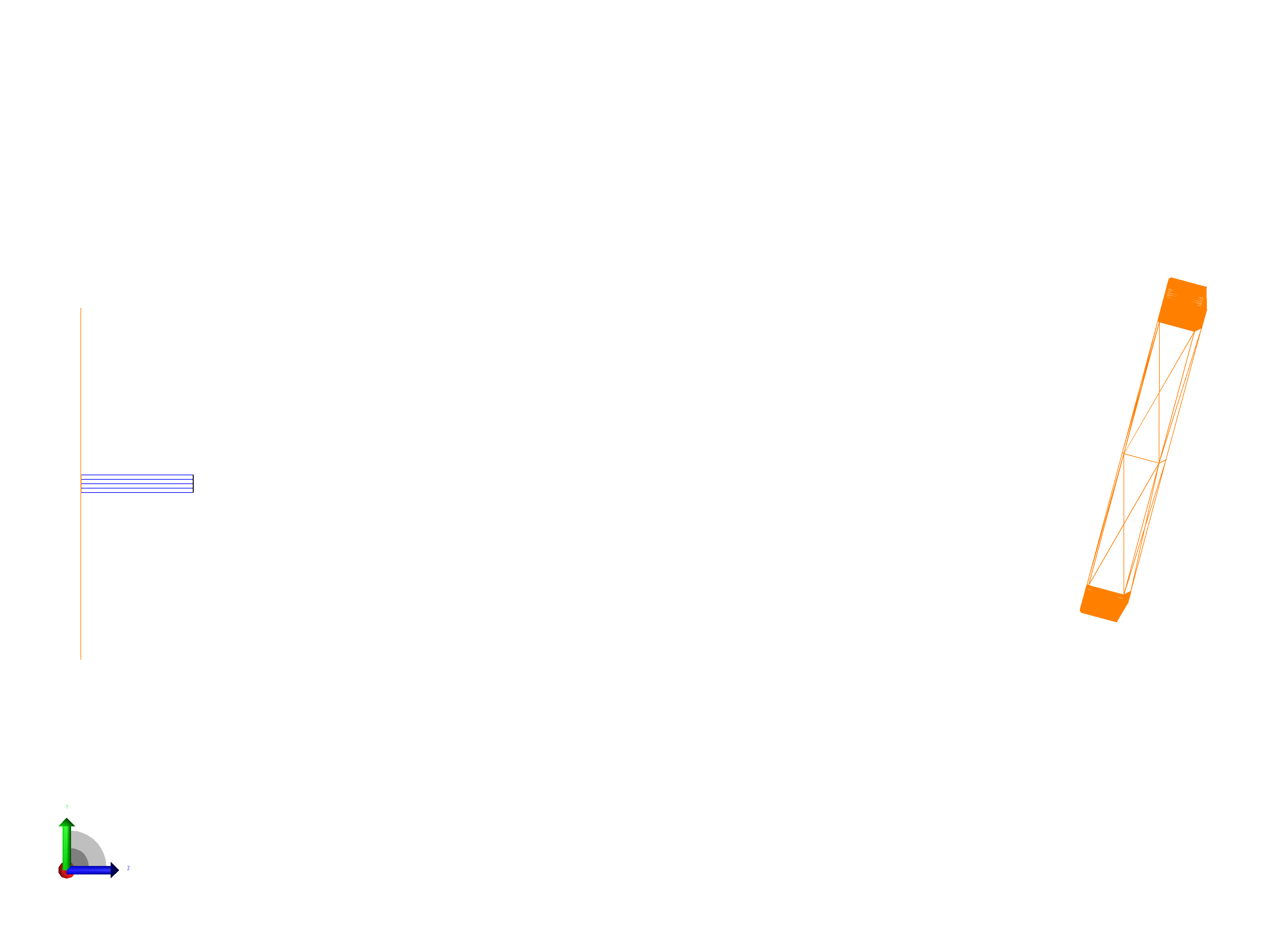
I’m having nothing but trouble with window orientation relative to the optical system, i.e. the basic set up.  First picture below is the window in CREO.  Second picture is import of that into OpticStudio.  The window is facing the wrong way (I would have to Z Tilt by 180) and seems to have a “displacement” from the window itself and the entrance port.  Do I have to tell the mechanical engineer to put the window in a specific orientation and origin point?  There have been WEEKS of sporadic back and forth on this.  

Did I mention that I’m almost out of my mind . . . ?

Thanks for any help you can provide.


icon

Best answer by mojtaba.falahati 21 January 2023, 00:12

View original

2 replies

Userlevel 1
Badge +2

Hi James,

As for the first part of your question, STAR module is only available in sequential mode, and in sequential mode you won’t be able to directly import a STP file into your lens file for STOP analysis.

As for the second part of your question, X,Y,Z Position and Tilt parameters of a NSC object set position and orientation of the object local coordinate system with respect to the global coordinate system, assuming the Ref. Object is 0. You may visualize the local axis in the 3D layout through Object Properties...Draw as shown below:

The CAD object local coordinate system is defined inside the CAD platform when saving a STP file. So, you may have two options here; first you can have your mechanical engineer define a local coordinate system in Creo to properly position and orient the CAD component in the local system and then customize the STP export by selecting the defined local system, and second, you can define a Null object with your desired orientation in NSC mode and then refer the CAD object to the Null object. 

I hope this helps. Please let me know if you have any other question.

Best,

Moj

Userlevel 1
Badge

Moj, 

Thanks for the clarification and guidance.  I am both elated and disappointed at the same time!  Elated because I can stop worrying about importing a CAD object for mixed-mode STAR analysis.  Disappointed because I can’t apply stress/thermal results to a CAD object.  I guess it all evens out.  Thanks again.

James

Reply