Air-gap doublets and deformation data
Doublets with small air gaps may overlap in an unphysical way when deformation data is added to the surfaces. In general, sequential models can’t automatically detect these kinds of collisions since the rays are instructed to go from one surface to the next without tracking their locations in 3D space.
The overlap can cause unexpected results in performance analyses such as spot diagrams and wavefront maps. They are detectable on layout plots and can be seen as negative pathlengths in raytrace results.
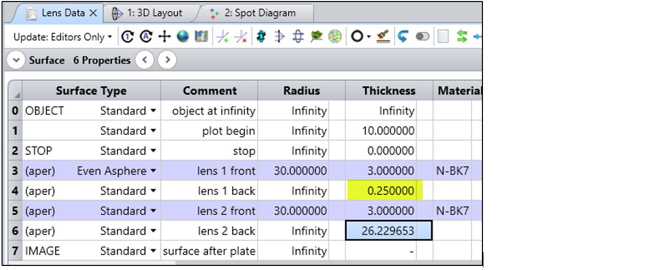
As an example, consider the two lenses below. There is an air gap of 0.25 mm between the lenses. We’ll add (artificial) deformation data that moves the back of the first lens 0.5 mm to the right, and the front of the second lens -0.3 mm to the left.


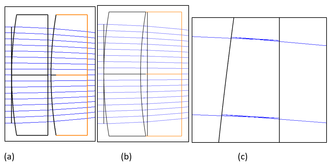
After applying the deformation data, the deformed surfaces are shown correctly in the 3D Layout plot. And if we zoom in, we can see the reverse raytrace.

c. Zooming in allows one to observe the reverse raytrace.
For small deformations that won’t be easily visible on the layout plot, the Single Raytrace will show a negative pathlength. And the Merit Function operand PLEN may be used to detect the condition.
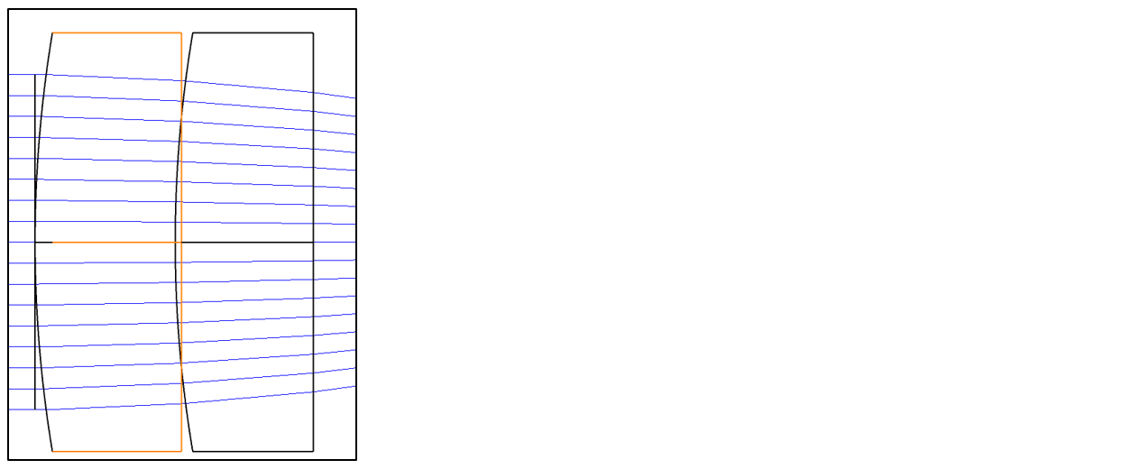
In the example below, I’ve adjusted the air gap between the lenses so that the parts overlap near the center but don’t at the edge. In the Merit Function, I can trace a fan of rays using the operand PLEN to measure the pathlength between surfaces 4 and 5. The incorrect, negative pathlength can be observed.


(The PLEN method requires some thought for a system that contains mirrors. Since the rays travel down the -Z axis after a mirror, the signs will be reversed after a reflection; the correct pathlengths will be negative, and the incorrect pathlengths will be positive.)


