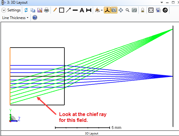
When looking at the POP result for off-axis system or off-central field, sometimes we may find the orientation of the beam spot is different to that in Spot Diagram.
Usually this is because the POP windows and Spot diagram are based on different coordinates. The result we see on the POP window is always a 2D grid of complex value lying on a plane that is perpendicular to the chief ray.
Initially the two orthogonal axes on this plane is decided by the local coordinate with a rule similar to how we decide 3D polarization from 2D Jones matrix as shown below.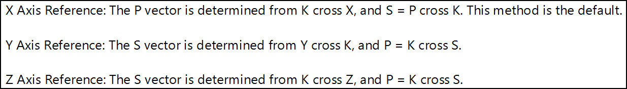
Let's call them beam axes from here.
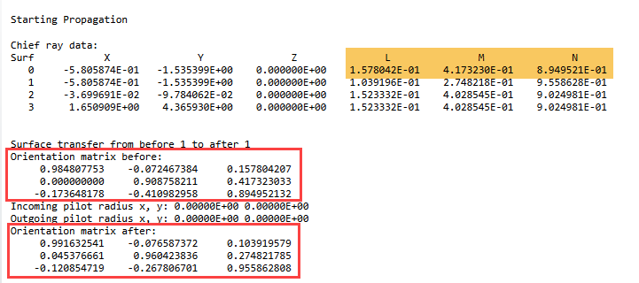
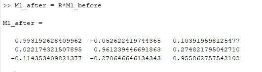
When the beam propagates to next surface, the beam axes won’t change (before refraction), but we should be able to describe the orientation relationship between the next surface’s local coordinates and the beam axes. This corresponds to a rotation matrix.
On the other hand, when the beam is refracted by the surface, the beam axes changes. Similarly, we also have a rotation matrix to describe the relationship between coordinates of the new beam axes and the surface local coordinates. These two rotation matrices are described in the Prop report as shown below.
We can use the following equations to convert the rotation matrix to TiltX/Y/Z.
https://support.zemax.com/hc/en-us/articles/1500005576822-Rotation-Matrix-and-Tilt-About-X-Y-Z-in-OpticStudio
We can make sure the Spot Diagram shows in same coordinate as in the POP window with the following method.
1. Add a dummy surface right after the surface you want to compare POP and Spot Diagram.
2. If there is a thickness between the dummy surface at its previous one, cut ant paste that value from previous surface to the dummy surface.
3. Use Tilt/Decenter Tool to automatically add a pair of CBs around the dummy surface.
4. Convert the “Orientation matrix after:” in Prop report on that surface to TiltX/Y/Z and type them in the CB.
5. On this dummy surface, now the beam axes is same as the local surface axes. You can compare Spot Diagram and POP result.