Why is the spot orientation different between POP and Spot Diagram
When looking at the POP result for off-axis system or off-central field, sometimes we may find the orientation of the beam spot is different to that in Spot Diagram.
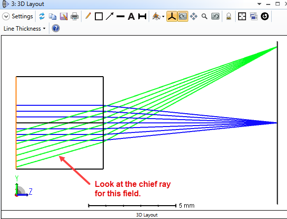
Usually this is because the POP windows and Spot diagram are based on different coordinates. The result we see on the POP window is always a 2D grid of complex value lying on a plane that is perpendicular to the chief ray.
Initially the two orthogonal axes on this plane is decided by the local coordinate with a rule similar to how we decide 3D polarization from 2D Jones matrix as shown below.
Let's call them beam axes from here.
When the beam propagates to next surface, the beam axes won’t change (before refraction), but we should be able to describe the orientation relationship between the next surface’s local coordinates and the beam axes. This corresponds to a rotation matrix.
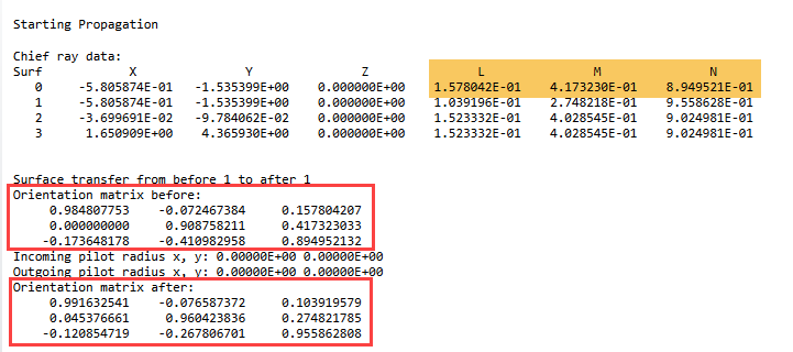
On the other hand, when the beam is refracted by the surface, the beam axes changes. Similarly, we also have a rotation matrix to describe the relationship between coordinates of the new beam axes and the surface local coordinates. These two rotation matrices are described in the Prop report as shown below.
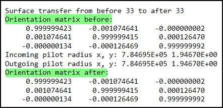
We can use the following equations to convert the rotation matrix to TiltX/Y/Z.
We can make sure the Spot Diagram shows in same coordinate as in the POP window with the following method.
1. Add a dummy surface right after the surface you want to compare POP and Spot Diagram.
2. If there is a thickness between the dummy surface at its previous one, cut ant paste that value from previous surface to the dummy surface.
3. Use Tilt/Decenter Tool to automatically add a pair of CBs around the dummy surface.
4. Convert the “Orientation matrix after:” in Prop report on that surface to TiltX/Y/Z and type them in the CB.
5. On this dummy surface, now the beam axes is same as the local surface axes. You can compare Spot Diagram and POP result.
Page 1 / 1
Hi Michael, I do not understand why POP result is exactly 45deg to Spot diagram. What is the theory behind? What should I believe, the Spot orientation that is correctly illustrated in meridional plane (or plane of incidence) that matches with Shaded model/3D viewer diagram or imagine that in reality my spot would be out of meridional plane rotated by 45deg. It is happening just as you mentioned in your article when I do POP for a simple folded system and I am not able to figure out why POP is giving me a shifted spot out of my meridional plane. You want to suggest that that is what happens in reality when you propagate a laser beam? I don't think so.
Krishna Kuchibhotla
Hello Krishna,
Thank you for reading the article.
Firstly I would like say if you have a specific file that you are investigating and couldn't figure out, I would encourage you to send it to support@zemax.com so that we can better answer it with your file.
Based on the information you provided, I would explain as below.
It's not necessary to be 45 degrees, which should depend on how you launch the beam. The rotation you are seeing is simply caused by different choices of coordinate reference.
In other words, the beam is not really rotated. It looks rotated because the XY axes used in POP window is not same as you see in the Spot Diagram.
Also, if your system includes a Diffraction Grating, this may cause some complexity and I would strongly suggest you send a mail to support inbox so that we can check with more details.
Please do not hesitate to let us know if you have more questions!
Michael Cheng
Hi Michael,
Thanks for your original posting on this topic.
I have a related question about the Orientation Matrices provided in a POP Propagation Report. First, though, I note that for the initial Orientation Matrix it appears that the “Y Axis Reference” scheme is the one utilized by POP (please let me know if this is not always the case).
My question is this: How is the Orientation Matrix after a surface calculated?
I tried applying a rotation matrix to the Orientation Matrix before the surface -- the rotation matrix being one that maps the incoming chief ray to the outgoing chief ray after refraction (based on the approach described in: https://math.stackexchange.com/questions/180418/calculate-rotation-matrix-to-align-vector-a-to-vector-b-in-3d , which I believe you have used previously for a ZPL script that tracks the (Jx,Jy) axes during polarization propagation). In any event, when I use this technique I get an answer that is close to what is provided in the POP report, but not exactly the same. The differences in the resulting Orientation Matrix elements are large enough that I don’t think the discrepancies can be attributed to a numerical error issue based, for example, on the exact way in which the rotation matrix elements are calculated. So I’m wondering if some other scheme is used to generate the Orientation Matrix after a surface? Can you help?
Thanks,
Jeff
Hi Jeff,
That’s a good question. I didn’t carefully check, but I think it should be very similar to what I did in the following macro as you also mentioned.
The key point is this coordinate needs to be tracked from initial surface. It will not work if you simply calculate the rotation matrix from f0,0,1] to chief ray LMN becuase it doesn’t include the correct rotation around the chief ray itself. You only made sure the beam plane is perpendicular to the chief ray, but the beam x and beam y axis are not at the correct position.
What I did in the macro is I create an initial jx, jy vectors, perpendicular to the ray. Whenever the ray changes the direction by refraction or reflection, I then use the method you mentioned to rotate the jx and jy axes. You can imagine the jx and jy axes will update at every surface. You cannot solely calculate this jx and jy axes with only chief ray vector becuase their orientation is an accumulated result from all previous surfaces. What the rotation matrix in POP shows is actually a rotation to exactly mapping the local (x,y,z) axes to (jx,jy,chief ray) axes.
I didn’t have time to test, but I think maybe I can update the macro to calculate this rotation matrix. It will be a multiplication of two rotation matrices. One is the rotation from local (0,0,1) to the chief ray vector. And another one is to rotate around the chief ray to match the (new x, new y) to the (jx,jy).
I hope this maeks sense to you.
Please let me know how you think.
This is an interesting question and thank you for discussion!
Michael
Hi Michael,
I don’t have a problem obtaining the first orientation matrix. It’s the second one, “after” the surface, that I’m not able to exactly replicate.
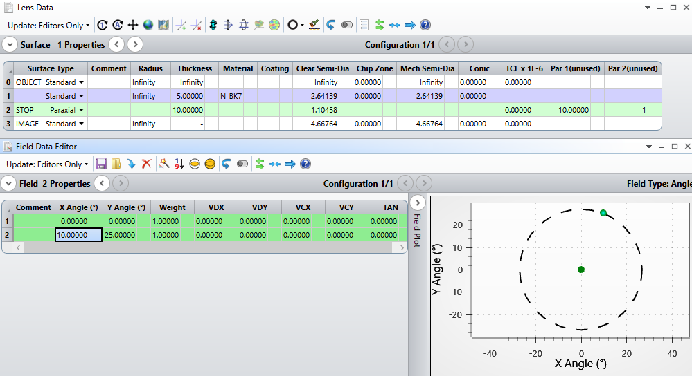
Let’s look at a specific simple example:
In particular, let’s look at the off-axis field (x=10 deg., y=25 deg.). Here is what the POP report shows for the first surface:
If we let the initial chief ray direction cosines define the vector k, and apply the “Y Axis Reference” by setting s = y cross k and p = k cross s, then the orientation matrix before the surface is simply M1_before = gs p k] which agrees exactly with the POP report:
However, if I then apply the rotation matrix R described in my previous posting (which aligns the local z-axis along the outgoing chief ray) to this first matrix, the resulting orientation matrix after the surface is M1_after = R*M1_before:
with the first two columns being slightly different than those of the matrix in the POP report. Again, the discrepancy isn’t that large, but it seems big enough to suggest that OpticStudio is using a different approach. This, of course, assumes that I’m computing the rotation matrix R correctly. I’ve checked it, and don’t see anything wrong, but maybe there is a mistake somewhere that I am missing…
Anyway, that’s what prompted my question.
Regards,
Jeff
Hi Jeff,
Thank you for the example. This makes the question clear. I tested but unfortunately I cannot reproduce this matrix either. I will see if I can get some more information from the development team.
Best regards,
Michael
Thanks Michael. The details associated with the POP orientation matrices are not very well documented.
Regards,
Jeff
Hi Jeff
I just want to let you know we are still working on this. One developer is going to check how it works in the code and I will update the Help File. We have some event this week and hopefully I can get something next week.
Best regards,
Michael
Great, thanks for the update Michael.
Regards,
Jeff
Hi Jeff,
I just got reply from development team and figured out the detail.
The syntax is defined as below.
x(n): an unit vector representing beam x axis after surface n.
y(n): an unit vector representing beam y axis after surface n.
k(n): an unit vector representing chief ray after surface n.
N(n): an unit vector representing normal vector on surface n.
s(n): an unit vector. This is not used in the final rotation matrix.
At surface 0, we calcualte x(n) and y(n) as below.
s(0) = normalize( (0,1,0) cross k(0) )
y(0) = normalize( k(0) cross s(0) )
x(0) = y(0) cross k(0)
Except surface 0, we calculate x(n) and y(n) as below.
s(n) = normalize( y(n-1) cross N(n) )
y(n) = normalize( s(n) cross k(n) )
x(n) = y(n) cross k(n)
The rotation matrix in the POP is composed by x,y,k as column vectors. Note the vectors x,y,k should be relative to local coordinate of the surface. When calculating the rotation matrix before surface n, we should use x(n-1), y(n-1), k(n-1) but relative to local coordiante of surface n.
I tested and this works for the example you provided.
Please let me know if this works for any other case you are looking at.
Thank you!
Thanks Michael. I would have never guessed this methodology! It’s good to know the details though.
A couple of minor points.
In the Syntax, you have y(n) listed twice -- I think the second one should be k(n) for the chief ray.
I am able to get this method to work if one change is made to the initial matrix calculation, namely reversing the order of the cross product so that: y(0) = normalize( k(0) cross s(0) ). Otherwise, all the other terms seem to be okay, at least for my simple example.
Regards,
Jeff
Hi Jeff,
Thank you for confirmation and check! You are correct. I re-checked and found it should be y(0) = normalize( k(0) cross s(0) ) !
That’s great it’s clear now. I have sent the Help file update and hopefully this will be in the next release of OpticStudio.
Best regards,
Michael
Hi Michael,
I’m struggling with a similar issue, so I’m eager to see the updated documentation in the next release.
I would like to be able to use the information in the propagation report and/or system prescription report to visualize each POP matrix in the global coordinate system. I would export data from beam files and use another program, like Python or MATLAB, to visualize the beams in space, so don’t worry about that. Is there a simple way to calculate the beam x,y unit vectors at each surface (before and after) in the global coordinate system, or do I need to rotate the initial chief ray into the global coordinate system, then somehow string together the rotations of beam axes through the POP report rotations system as you outlined above?
Best,
Evan
Hi Evan,
Sorry for late reply. I was supposed to sent this yesterday.:)
For your plan, I think it’s possible. Here are some information that I think you will need when using Matlab or Python.
2. Here is an example how you can get rotation matrix for a surface. You can check the sample 07 in the ZOS-API Help file for full example code in all 4 languages (MATLAB, Pyton, C#, C++).
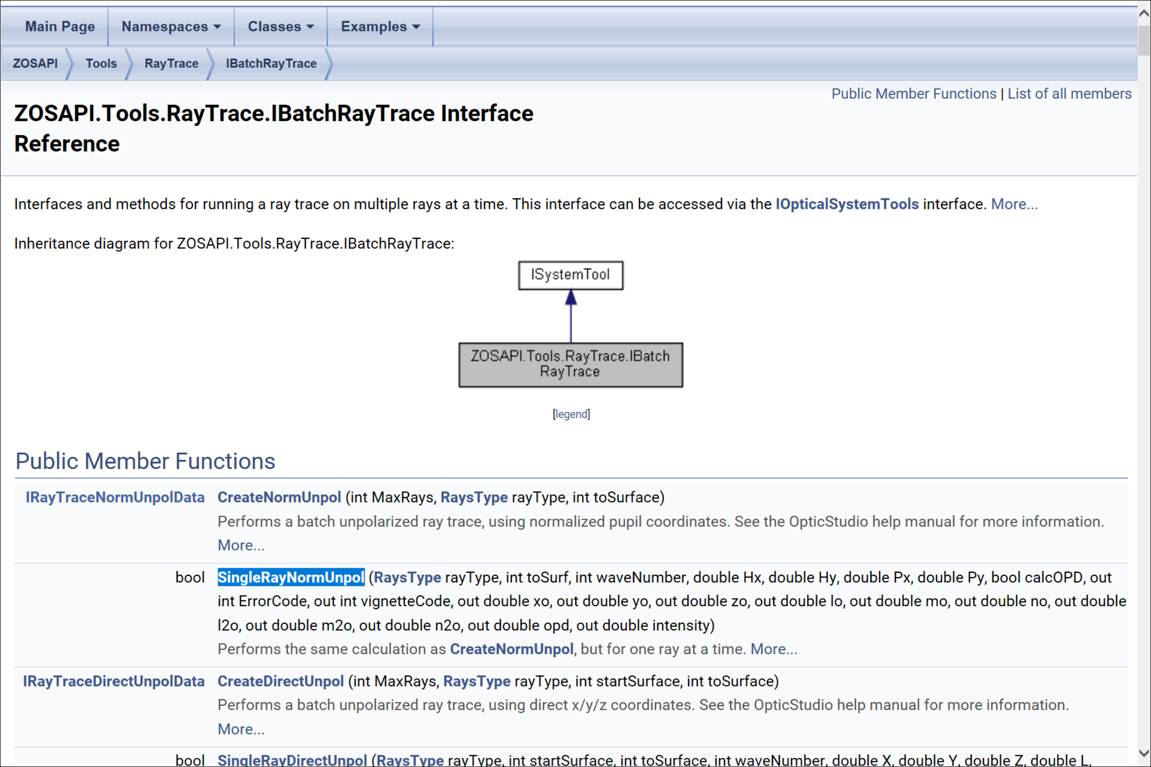
3. To get the ray data at each surface, you have many tools. You can simply use operand like RAGX/Y/Z. Or you can us the function like SingleRayNormUnpol as shown below.
4. For the beam xy unit vector, unfortunately, I think this one is most tricky and there is probably no simple way, although it’s still doable. One option is you can export the Prop Report data in POP window manually and parse it in Python/Matlab. Another option is you use the ray data and calculate it following the instruction we discussed in the post thread.
I hope this helps.
Please let me know if you have any questions.
Thank you.
Hi Michael,
Thanks for the reply! Could you clarify:
The rotation matrix in the POP is composed by x,y,k as column vectors. Note the vectors x,y,k should be relative to local coordinate of the surface.
Does this mean if I am able to parse the POP report, I will have the x,y,k vectors without additional calculation? To be explicit, is each matrix composed of x,y,k vectors like this?
And, if that is the case, which rotation matrix would rotate these unit vectors to the global coordinate frame? If k(n) or k’(n) is the chief ray unit vector before/after, then would it suffice to know the chief ray unit vector in the global frame as it leaves surface n in order to find x’(n),y’(n),k’(n) in the global frame?
Thanks,
Evan
Hi Evan,
I’m sorry for late reply.
You are correct the x,y,k vectors are composed as you showed into a rotation matrix.
Note the x(n),y(n),k(n) in my explanations above are “after” the surface. For before the surface, you can use x(n-1),y(n-1),k(n-1).
To answer your second question, let’s first mention there are 3 coordinate systems here.
beam axes
surface local axes
global axes
The rotation matrix in the POP report can be used to do the conversion from the (2) to (1).
And for every surface, there is also a rotation matrix that can do the conversion from (3) to (2). You can check the sample 07 in the ZOS-API Help file for full example code in all 4 languages (MATLAB, Pyton, C#, C++) about how to get this rotation matrix.
So in conclusion, with the two rotation, you should be able to convert (1) to (3) by adequately using the two rotation matrices.
Hi Michael,
Could you answer the following question to clarify further?
Should the conversion from (2) surface local axes (l,m,n) to (1) beam axes (x,y,k) be described as
instead of
x(n) y(n) k(n)]’ = Anl m n]’
Regards,
Hiroaki
Hi Hiroaki,
Sorry for confusion. I checked and I think my previous sentence “The rotation matrix in the POP report can be used to do the conversion from the surface local axes to beam axes.” is not correct. It’s actually opposite.
So, assuming
A is the surface orientation matrix
/l;m;n] is a vector defined in surface local axes.
/l’;m’;n’] is the same vector but in surface beam axes.
We then have
hl;m;n] = A>l’;m’;n’]
The x(n), y(n), k(n) are the 3 axes, in beam axes system, represented in surface axes system. In other words,