[Webinar] Mechanics of an Ansys Zemax Workflow: OpticStudio – OpticsBuilder – Speos [Q&A]

  • 28 September 2022
  • 11 replies
  • 210 views

Badge +3

This thread is dedicated to the upcoming webinar: Mechanics of an Ansys Zemax Workflow: OpticStudio – OpticsBuilder – Speos. Any questions received during the webinar will be responded to as a reply on this thread. Feel free to post your own questions! The speaker will be notified and will respond as long as the thread is still open.

Be sure to subscribe to this thread if you want to see additional discussion regarding this webinar topic. The thread will be open to new replies for a limited time following the event.


[The event has concluded]


Webinar details

Date: Thursday, September 29th

Time: 6:00 - 7:00 AM PDT | 11:00 - 12:00 AM PDT

Presenter: Flurin Herrin, Application Engineer II

Abstract:

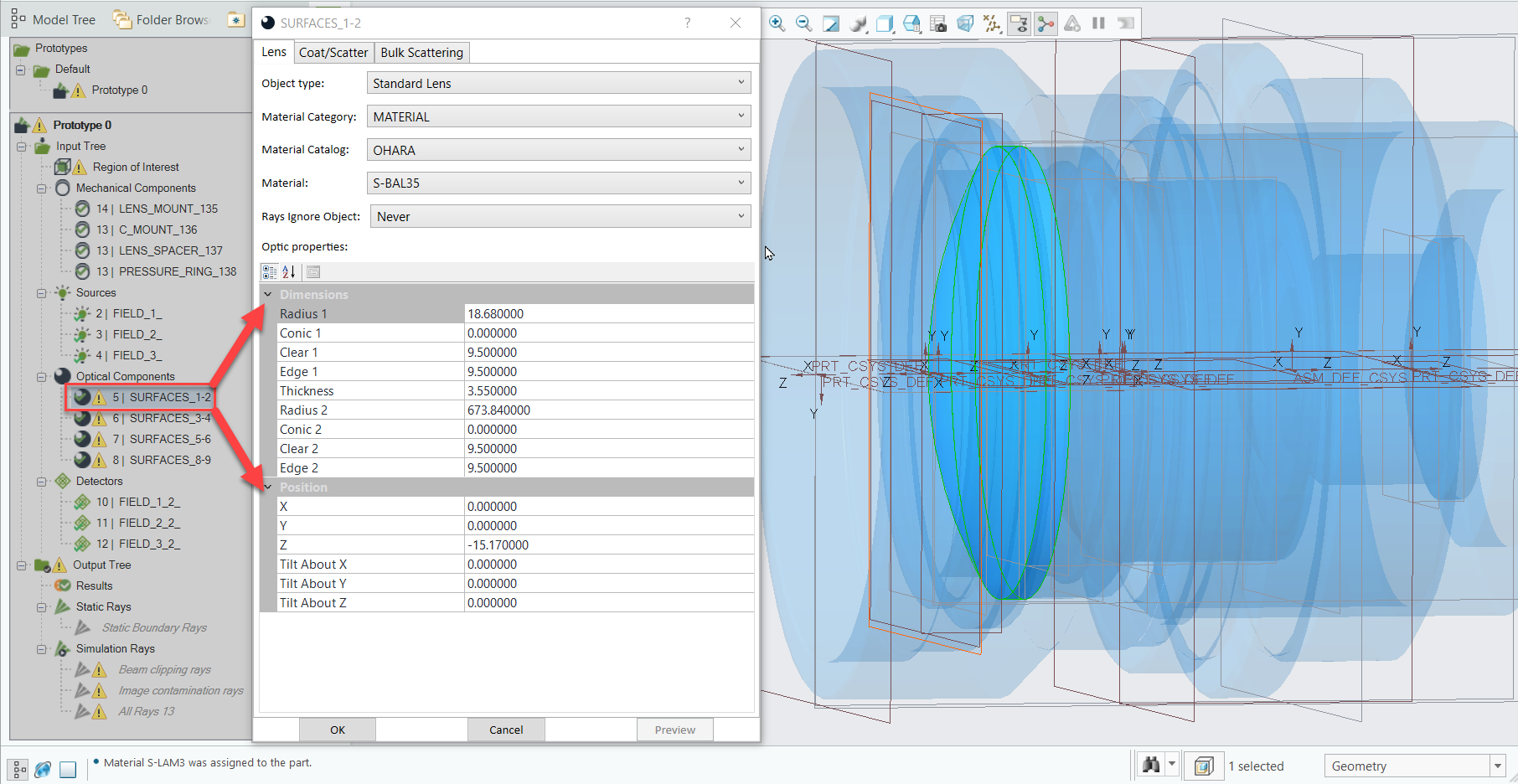
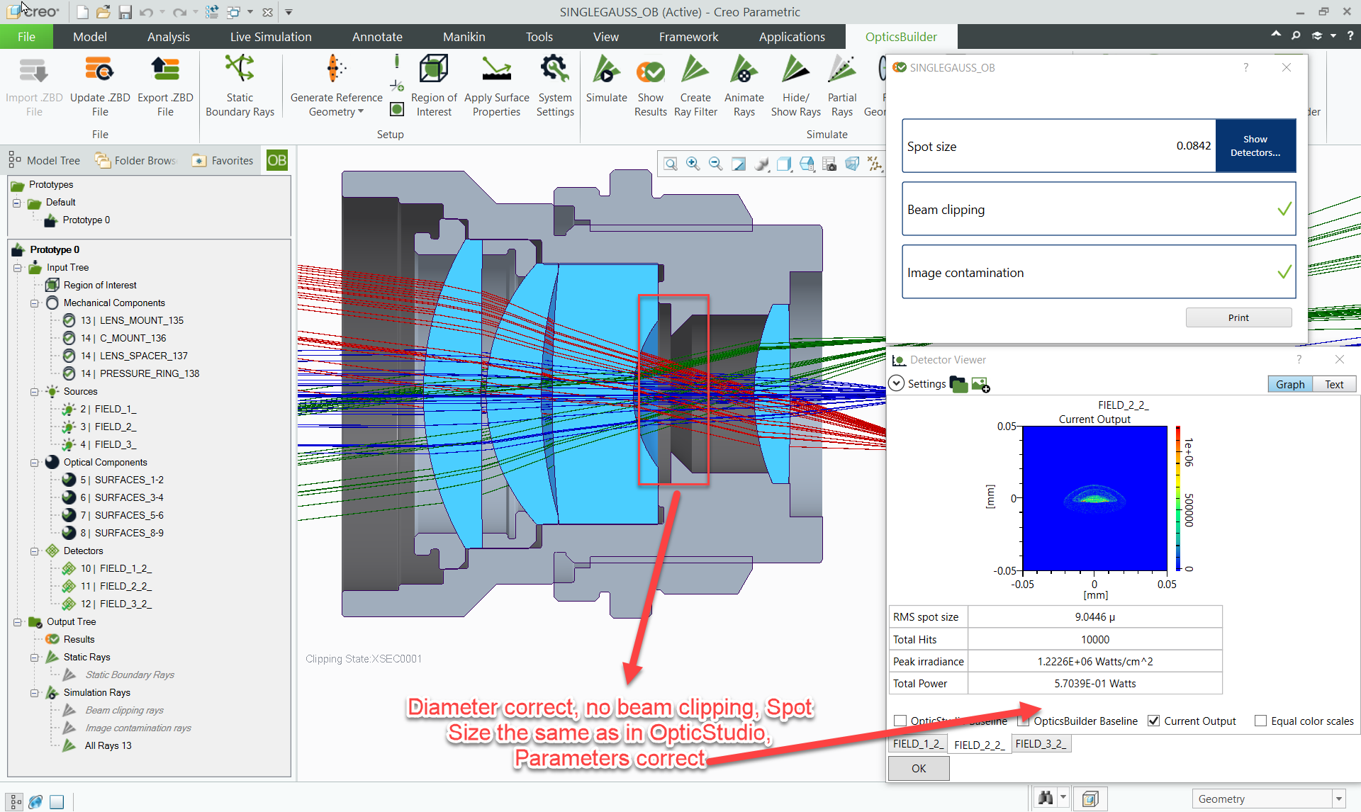
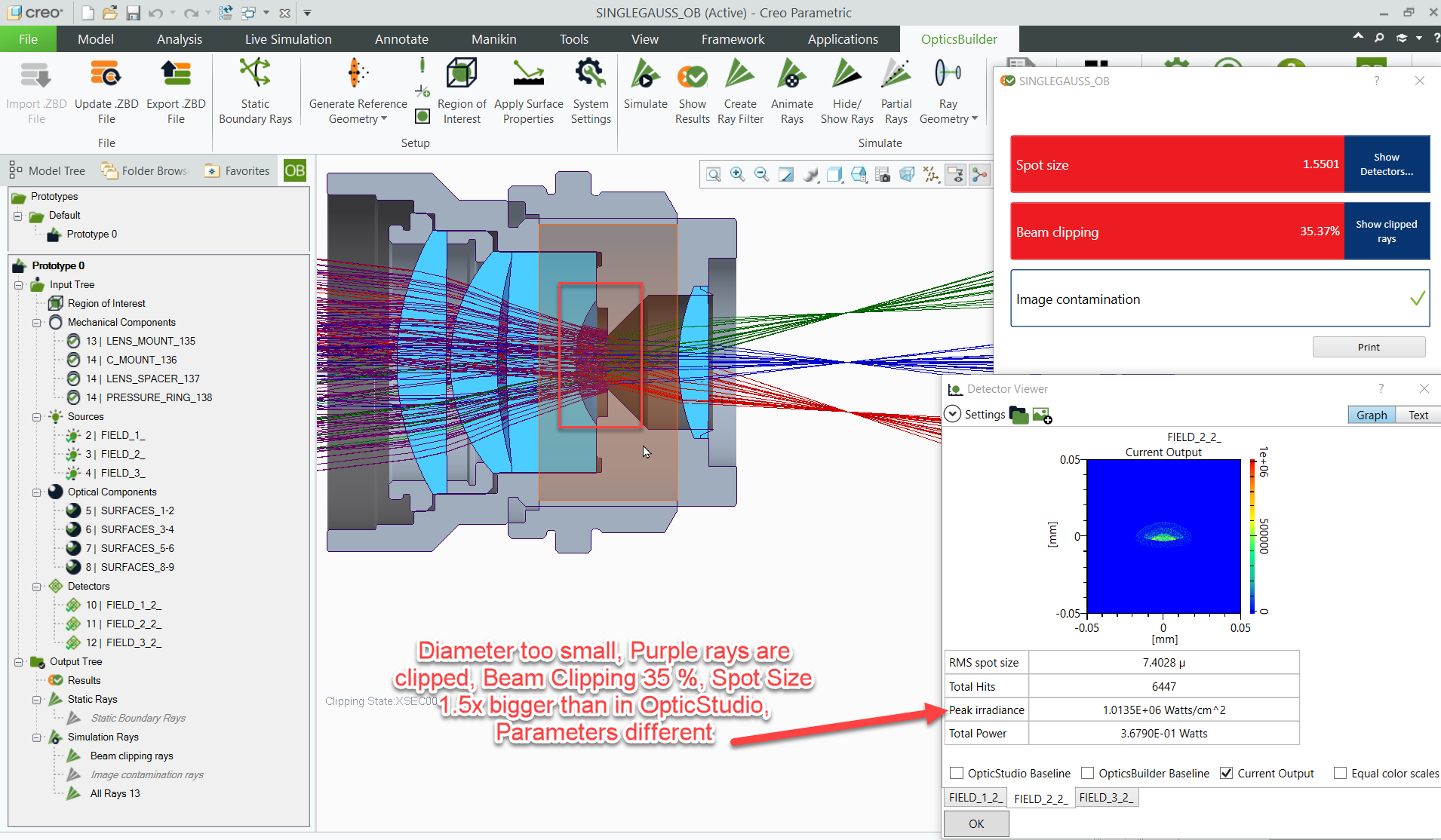
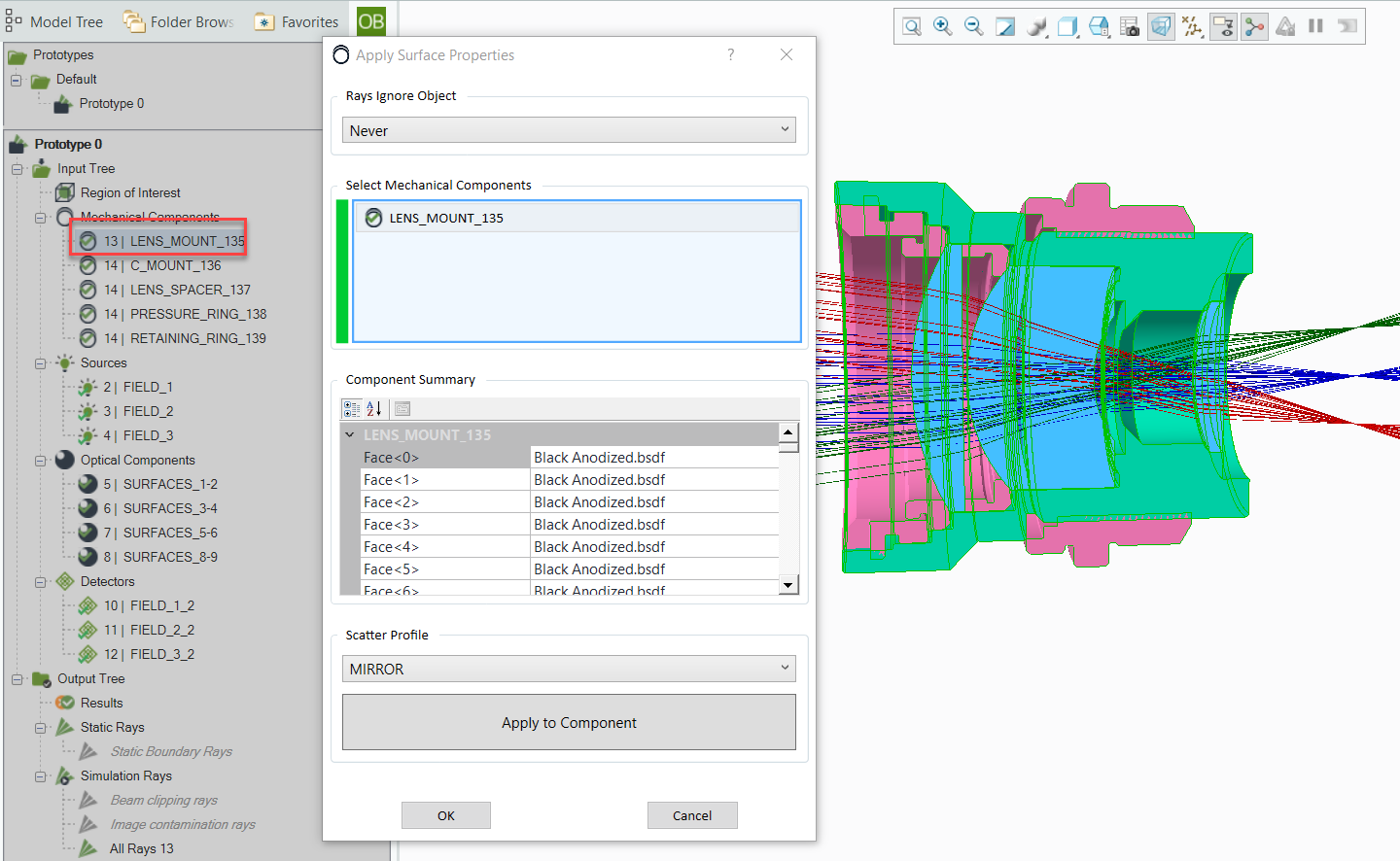
Join Flurin Herren, Optomechanical Engineer of Ansys Zemax, on a webinar which takes the user through the workflow of an optomechanical system from design all the way to stray light analysis and optical performance validation. With a focus on the software mechanics and the conversion between Ansys Zemax software. Starting off in Zemax OpticStudio with the Design, going into Creo Parametric 7 and Zemax OpticsBuilder which covers the optomechanical validation and finally using the Ansys Speos add-in of Creo Parametric 7 to perform Stray Light analysis.

Allie 1 year ago

Watch the recording

A recording of this webinar may be accessed here: Mechanics of an Ansys Zemax Workflow: OpticStudio – OpticsBuilder – Speos

View original

11 replies

Badge +3

@Shaojie. Chen , @Plinio.Pinzon , @Pragati , @Yisi.Liu 

Q: What is the difference between the Stray light analysis in OpticStudio NSQ and that in SPEOS? 

A: As you can re-import the .ZBD file including the mechanical components into OpticStudio non-sequential you can actually choose between doing the Stray Light Analysis in OpticStudio Non-sequential or in Speos. And as there are similarities there are also key differences between these two approaches: The first order of SL Analysis is possible in both platforms but for example when it comes to the Scattering library there are a lot more models in Speos or in terms of detectors you can use one single detector to do different analysis (layers) such as photometric or colorimetric in Speos. On the other side with Sources, you`ll have more choices in OpticStudio Non-sequential.

However, we will do a webinar on Stray Light Analysis in Speos soon. Also including a comparison with the Stray Light Analysis possibilities within OpticStudio non-sequential. In the meantime, if you are intertesed in specific funcuitnality of Ansys Speos please see Ansys Speos | Optical System Design Software or reach directly out to my colleague Julien Duchene (julien.duchene@ansys.com).

Badge +3

Q: What is the best way of considering a random vibration environment? That is when the optical assembly is subjected to a random vibration and thus having an effect on the lenses.

A: In the case of random vibration, I would suggest the following workflow: Design the optical system with Zemax OpticStudio (Sequential mode), convert the system to your CAD Environment with a .ZBD file and carry out the optomechanical validation with Zemax OpticsBuilder. After that you can convert the optomechanical system as a STEP file to a FEA Software (E.g. Ansys Mechanical) and apply the random vibration load to the optomechanical system. After that you can re-import the max and min structural load as a FEA dataset back into OpticStudio with the STAR Module and see the influence of the max and min vibration states on the optical performance.

This approach is limited to the max and the min of the structural load onto the optical performance. If you want to apply vibration fatigue or other time-depended analysis, you can try to connect the Speos with Mechanical directly via the Ansys Workbench ( which is an entirely different Approach, but closer to workflow which I have showcased here). For more information on the Speos-Workbench approach, please contact my colleague Julien Duchene, julien.duchene@ansys.com

And if you would need support with a specific Zemax file or project do not hesitate to reach out to support@zemax.com 

Badge +1

​​​​​

Q: What is the difference between the Stray light analysis in OpticStudio NSQ and that in SPEOS? 

A: As you can re-import the .ZBD file including the mechanical components into OpticStudio non-sequential you can actually choose between doing the Stray Light Analysis in OpticStudio Non-sequential or in Speos. And as there are similarities there are also key differences between these two approaches: The first order of SL Analysis is possible in both platforms but for example when it comes to the Scattering library there are a lot more models in Speos or in terms of detectors you can use one single detector to do different analysis (layers) such as photometric or colorimetric in Speos. On the other side with Sources, you`ll have more choices in OpticStudio Non-sequential.

However, we will do a webinar on Stray Light Analysis in Speos soon. Also including a comparison with the Stray Light Analysis possibilities within OpticStudio non-sequential. In the meantime, if you are intertesed in specific funcuitnality of Ansys Speos please see Ansys Speos | Optical System Design Software or reach directly out to my colleague Julien Duchene (julien.duchene@ansys.com).

 Thank you for your reply and an amazing webinar @Flurin Herren . I look forward to the stray light analysis webinar too!

Userlevel 6
Badge +2

Watch the recording

A recording of this webinar may be accessed here: Mechanics of an Ansys Zemax Workflow: OpticStudio – OpticsBuilder – Speos

Badge +3

Q: What is the maximum *.ZBD file size you can bring into OpticStudio?

A: There is no maximum as such, the larger the file the longer it will take to load so you will just need to be cognizant of loading times with larger files.

Badge +3

@Ronald.Taylor 

Q: What other CAD systems are supported with OpticsStudio and OpticsBuilder and Speos?

A: Zemax OpticStudio is a standalone software, Zemax OpticsBuilder is an add-in for Creo Parametric 4,5,6 and 7 and Ansys Speos is an add-in for Siemens NX, Creo Parametric or a standalone version on the engine of Ansys SpaceClaim.

Badge +3

@kareem.el sherbiny 

Q: Is optics builder available for autodesk products?

A: No, Zemax OpticsBuilder is currently avaible for Creo Parameteric 4,5,6 and 7. We are exploring to find new CAD partners in the near future.

Badge +3

@Joni.Mici @Steven.Smith 

Q: Can the Speos workflow accommodate mechanical/thermal stresses in the opto-mechanical design process?  / Is Optics builder compatible with Solidworks? Or just Creo?

A: Yes, once the optomechancial validation with OpticsBuilder is carried out and the user changes to the Speos add-in, we can recover the mechanical deformation on the optical and mechanical surrounding inside Speos with direct link between Ansys Mechanical and Speos in Workbench. It uses warping to rebuild the deformed geometry in the non-sequential study. You can also apply gradient refractive index, but it does require a bit more effort than for example with the STAR Module. For more information there on Ansys Speos, please see Ansys Speos | Optical System Design Software or reach directly out to my colleague Julien Duchene (julien.duchene@ansys.com).

For the STAR Module approach: Design the optical system with Zemax OpticStudio (Sequential mode), convert the system to your CAD Environment with a .ZBD file and carry out the optomechanical validation with Zemax OpticsBuilder. After that you can convert the optomechanical system as a STEP file to a FEA Software (E.g. Ansys Mechanical) and apply structural and/or thermal load to the optomechanical system. After that you can re-import the thermal and structural load as FEA datasets back into OpticStudio with the STAR Module and see the influence of the max and min vibration states on the optical performance. A good example for this workflow is our CubeSat Project (4 Part Article Series): From Concept to CubeSat Part 1: Using Ansys Zemax Software to Develop a CubeSat System – Knowledgebase 

Zemax OpticsBuilder is currently available for Creo Parameteric 4,5,6 and 7. We are exploring to find new CAD partners in the near future.


Badge +3

@bill.g.zhang 

Q: Can you evaluate wavefront error, MTF, EE, Distortion, Relative Illumination, etc in OpticsBuilder? / Can you edit the lens in OpticsBuilder?

A: As the Ray Trace Engine of OpticsBuilder is built on the non-sequential ray trace engine of OpticStudio, only non-sequential analysis approaches are possible. Let me explain this a bit further: In Sequential Mode, we can calculate the wavefront error because we have chief & marginal rays and a defined exit pupil for the system. In Non-Sequential Mode, none of these definitions exist. Rays simply travel through space after they are launched from the source, but there are no chief or marginal rays.

On your second question: Yes we can edit Dimensions, Material, Coating, Positioning and many other things in OpticsBuilder (See image below) and even if we apply these changes, the lenses are still eligible for ray traces, so you can see the new Spot Sizes, Total Power etc..


Badge +3

Q: instead of NSC mode detector viewers, can you make those comparisons with spot diagrams or wavefront maps from sequential mode? / can you show the workflow when you find a spot size error or beam clipping? Do you need to buy licenses for both creo and speos? Or is the speos functionality included in creo?

A: As the Ray Trace Engine of OpticsBuilder is built on the non-sequential ray trace engine of OpticStudio, only non-sequential analysis approaches are possible. Let me explain this a bit further: In Sequential Mode, we can calculate the wavefront error because we have chief & marginal rays and a defined exit pupil for the system. In Non-Sequential Mode, none of these definitions exist. Rays simply travel through space after they are launched from the source, but there are no chief or marginal rays.

Workflow when Spot Size differences or Beam clipping occurs: 


And finally, you will need a Ansys Speos License for Creo Add-in Speos.


Badge +3

Q: How do you define the optical properties of the mechanical components? E.g. transmission, reflectivity..

A: In order to edit the Surface Properties of mechanical components in Zemax OpticsBuilder, you can right click on the component in the OpticsBuilder model tree (The same approach as edit optical components). After that the mech. part is highlighted in the Model viewer and you can apply surface properties to each face of the mechanical part. The default surface property of the mechanical components is Black Anodized. (See Image below):


Reply