
The easiest way to tolerance an off-axis mirror

  • November 17, 2023
  • 3 replies
  • 1236 views

Forum|alt.badge.img+1

Many off-axis mirrors are constructed using an off-axis aperture on a “parent” mirror.  This can make tolerancing difficult, since the perturbations must be applied at the vertex of the off-axis aperture.  Tolerancing can be easily and correctly set up using the Composite surface and Tilt/Decenter tool in OpticStudio, as shown below for an off-axis parabola (OAP).

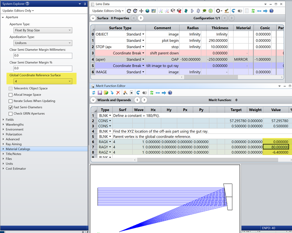
In this OAP file, the parent is shifted down from the stop so that the gut ray (at Px=Py=Hx=Hy=0) strikes the vertex of the off-axis mirror.  We have set the global coordinate reference to the parent mirror, and used RAGX/Y/Z operands in the Merit Function to locate the vertex of the off-axis part.

An off-axis parabola created by adding an off-axis aperture to a parent parabola

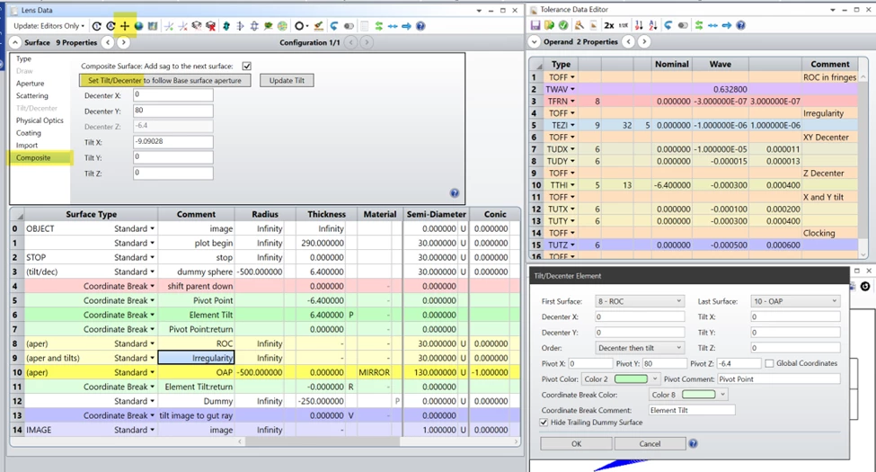
To prepare for tolerancing, we use the vertex coordinates to set up a pivot about the off-axis vertex, using the Tilt/Decenter Elements tool (located in the toolbar of the Lens Data Editor).  We insert two Composite surfaces before the OAP, and use the Set Tilt/Decenter button to locate the two at the vertex of the off-axis mirror; the sag of these surfaces will be added to the OAP sag.

For tolerancing, a TFRN operand can be used to adjust the ROC of surface 8.  TEZI is used to add irregularity to surface 9, starting at Zernike term 5 so that piston, tilt, and defocus terms are not added in the irregularity.  TUDX/Y and TUTX/Y/Z operands control the decenters and tilts, found in surface 6.  Z-decenter can be added using TTHI on surface 5. 

Setting up for tolerancing, with all perturbations correctly located at the vertex of the OAP

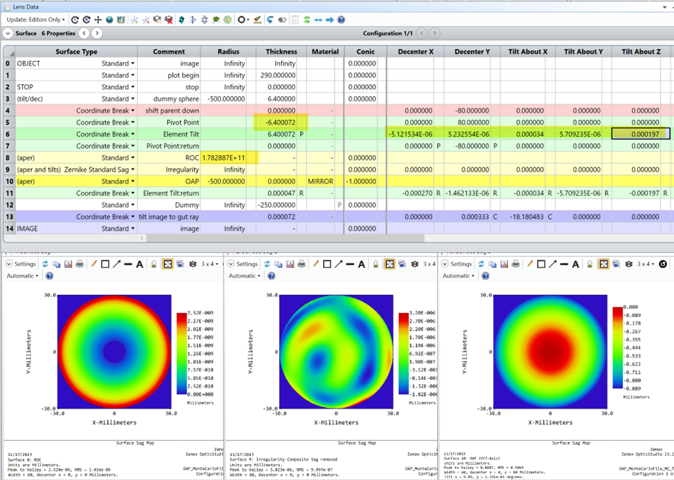
Saving a Monte Carlo file shows the changes that are made for tolerancing.  Surface 9 is converted to a Zernike Standard Sag for adding irregularity.  The ROC is adjusted on Surface 8.  And tilts and decenter perturbations appear on surface 6.  The Sag Maps can be used to observe the surface perturbations on surfaces 8, 9, and 10; the total sag of the surface (the sum of surfaces 8, 9, and 10) is held in surface 10.

A Monte Carlo file showing the modifications made during tolerancing


3 replies

aajr2022
  • Single Emitter
  • February 10, 2026

Thank you for this OAP tolerancing method. However, for RoC tolerancing why dont we use TRAD directly on the base composite (mirror itself). Why having one more composite surface (surface 8 ) with infinite RoC surface nominal and use TFRN with such small fringes  


Forum|alt.badge.img+1
  • Author
  • Zemax Staff
  • February 10, 2026

Hello!   This surface has an off-axis aperture.  If you change the vertex radius of curvature of the parent mirror, the off-axis vertex will change positions in Z!  Also, the power/defocus change will be centered on the vertex of the parent mirror.  At the off-axis aperture, this will look like tilt, not power!   Which is not physically correct due to how mirrors are polished; the power error will be centered on the off-axis aperture.

You can try this out yourself by looking at the Sag Map for the base surface.  Make sure that the “off-axis coordinates” option is turned off.  If you change the ROC, you get tilt and a change in Z position at the off-axis aperture.

Instead, we want to add a power error using Composites.  But be careful to *not* use TRAD on the Composite, either!  Radius of curvature is nonlinear, so you can’t add two ROCs and get the result that you expect.  Power/defocus is measured as a change in Z at the edge of the part, and it does add linearly, so that’s the correct one to use here.

ROC (radius of curvature) can be divided in half on the parabolic mirror between the add-on and base composite surfaces, but not Spherical surface | Zemax Community


aajr2022
  • Single Emitter
  • February 11, 2026

Hello Erin,

Thank you for explanation. It makes sense according to the fact of off-axis mirror. However, I am still thinking how TFRN tolerance on compsite surface which correctly applied a change in Z and in turn results R+deltaR (of composite surface) around 10^12 can be related to the R+deltaR of the base mirror. That is what matter for manufactoring these days as they prefer R+deltaR not Newton ring fringes.