Hi Zemax community, a question regarding why ROC (radius of curvature) can be divided in half on the parabolic mirror between the add-on and base composite surfaces while keeping the perfect focus, but not the same case for the spherical surface type, is often asked. Here we will give an on-axis mirror example to demonstrate the math correlation behind this concept.
First, let’s start with an on-axis spherical mirror (Example file: 1_SphericalMirror.ZAR):
In this example, the incident rays originating from the center of sphere curvature are reflected by the spherical mirror surface, back along the original way. The radius of curvature and back focal length is -100mm. No optical aberration is introduced in this example, the spot diameter will be perfect.
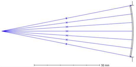
Fig 1. Spherical mirror layout
Now let’s make a comparative file with an add-on composite surface at the front of the base spherical surface (Example file: 2_SphericalMirror_WithAddOnComposite.ZAR). To main the same EFL as the first file with the add-on composite surface, the spherical radius of curvature -100mm is divided in half to be -200mm, evenly on the add-on and base composite surface (according to lensmaker’s equation). The spot diameter result in example 2 deviates from the perfect focus, 353.6micron spherical aberration is generated.
For the second comparative group: we will use the on-axis parabola mirror (Example file: 3_OnAxisParabola.ZAR & 4_OnAxisParabola_WithAddOnComposite.ZAR):
In the example file 3_OnAxisParabola.ZAR, incident rays from infinity come to perfect focus. In the example, we used the parameters below: ROC = -500 mm, Effective focal length = ROC/2 = -250 mm, conic constant value is –1(which makes reflective surface a parabola).
Now let’s make a comparative file with an add-on composite surface placed at the front of the base parabola surface (4_OnAxisParabola_WithAddOnComposite.ZAR). Divide the parabolic mirror ROC in half to be evenly on the add-on and base composite surface with ROC = -1000 mm. Then check the image performance (spot diameter), and we will find out the image is still perfect.
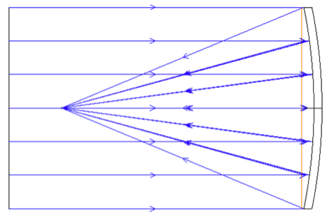
Fig 2. Parabolic mirror layout
The math behind this is related to the surface sag slope variation curve:
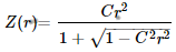
For the Standard (non-aspheric) surface, the sag equation is:
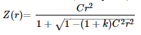
Here, r represents the radial distance from the optical axis, k is the conic constant, Z is the sag of the surface parallel to the optical axis, and C is curvature, which is the inverse of the radius.
For the spherical surface, k=0, the sag equation is
For a parabola, k = -1, the sag equation will become:
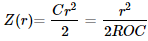
Where C is the curvature and ROC is the radius of curvature.
For the spherical surface, the sag slope is not constant value (sag equation is not linear related to the radial height).
For the parabolic surface, it has a simple form that is linear in r:

For the linear equation, the variance of the slope will be 0, which means in the exhibited case, the reflected rays at different radial heights will share the same slope in the comparative group the divided slope on the add-on and base composite will both be

. If the rays are focused at the focal point, there should be no aberration introduced.
While for the spherical surface, the reflected rays at different radial heights will deviate from focus to the same spot since there is slope variance on the reflected surface, so spherical aberration will be expected if the reflected surface divide into half.
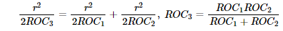
In both cases, according to lensmaker’s equation
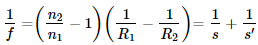
, s = distance of object from lens, s' = distance of image from lens, f = focal length of the lens the EFL will remain the same since the radii of curvature are split in half. The generated sag will be the same in comparative group files.