


In a previous tech tip, we discussed the importance of the choice of materials and coatings for infrared (thermal) systems in achieving an optical system design to match imaging performance targets. But the story doesn’t end with the optical components; an accurate representation of the blackbody emitter and detector are also required!
Modeling a radiating object
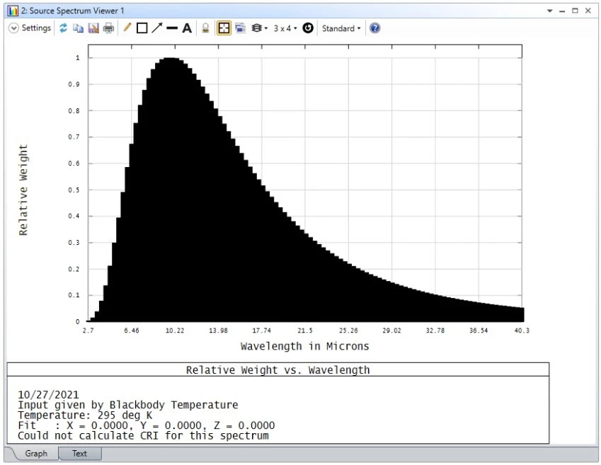
Thermal radiation of objects can be easily and accurately modelled using the Black Body Spectrum setting in OpticStudio, defined by a temperature in Kelvin. As an example, say we are designing a camera to image object radiation in the target temperature range between -45°C and +75°C. We can use Planck’s blackbody radiation law to determine that we need a wavelength range from 3 to 40 μm. OpticStudio then determines the relative weights of each wavelength in this range for the desired blackbody.
Of course, to properly model the system, the material information needs to cover the whole range of wavelengths emitted from the object of interest. This can be edited as necessary, then you can raytrace through your system and retrieve the irradiance map on your sensor.
Modeling detector wavelength sensitivity
But let’s examine our sensor simulation; each detector has its own spectral responsivity range! For instance, common infrared thermal devices are limited to the long-wave infrared range, between 8 and 14 μm, so we should limit the simulated detector to focus on that part of the spectrum.
We can accomplish this using the X_WAVERANGE(n, a, b) filter string, which limits our analysis to only rays hitting detector number “n” between wavelengths “a” and “b”, measured in micrometers. For our example case, we would use X_WAVERANGE(n, 8, 14). Filter strings may be applied within the ray trace console or on the detector viewer.
Now we’ve modelled our source and the spectral range of our detector. If you wanted to improve your detector model even further, you could apply a relative spectral sensitivity weighting to your model by using a table coating or in post-processing.
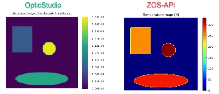
Translating from incoherent irradiance to a temperature map
Finally, after running your raytrace, you’ll receive incoherent irradiance on the detector. It’s possible to use the API to post-process the irradiance map and turn it – after calibration – into a temperature map :
You may want to check our knowledge base article for further details, sample files and sample code:
Infrared thermometer and thermal camera simulation using OpticStudio – Knowledgebase (zemax.com)