Solved

OpticsTalk: Coordinate Breaks - Usage & Applications


Userlevel 2
Badge +1

Coordinate Breaks are a powerful tool to model off-axis and other non-rotationally symmetric systems. However, specifying parameters like arbitrary pivot points in 3D space is non-trivial in a sequential-based coordinate system. In this OpticsTalk, we'll take a closer look at setting up Coordinate Break surfaces and utilizing functions like the Coordinate Return and different Solve types to more efficiently set up complex systems.


This talk is hosted by Angel Morales, an optical engineer from Zemax's US Customer Success Team.

icon

Best answer by Angel Morales 10 July 2020, 02:58

View original

10 replies

Userlevel 5
Badge +1

Hi all!


Thanks again for attending and participating in our OpticsTalk. Attached to this post are the slides presented along with the starting and ending points of the examples shown. We'll dig a little deeper into the questions brought up during the discussion, but I wanted to share these as soon as possible to get them in your hands.


Let us know if there are any further questions or other applications of Coordinate Break surfaces you'd like to see! Thanks everyone!


~ Angel

Userlevel 4
Badge +2

Thank you all very much for attending the OpticsTalks and participating to the discussion.

I also want to thank Angel for all the good work!


During the talk, I shared a few ressources which I find interesting about this topic.


rotation matrix


coordinate return


global coordinate in sequential mode


Chanllenge your Coordinate Break skills with this tutorial


Roll of a doublet


https://my.zemax.com/en-US/Knowledge-Base/kb-article/?ka=KA-01638


https://my.zemax.com/en-US/Knowledge-Base/kb-article/?ka=KA-01437


https://my.zemax.com/en-US/Knowledge-Base/kb-article/?ka=KA-01506


https://my.zemax.com/en-US/Knowledge-Base/kb-article/?ka=KA-01433


https://my.zemax.com/en-US/forum/threads/6e5c7f12-9b94-ea11-a811-000d3a329613#fa55192e-ab94-ea11-8b71-00155dd4890c


We started a couple of interesting discussions about use cases and common issues, feel free to continue the discussion in this forum thread.


-What is the typical kind of systems you use coordinate break with?    

-How do you currently use coordinate breaks during tolerancing?  

-What do you find particularly difficult when working with coordinate breaks?


Userlevel 3
Badge

How does one participate in these OpticsTalk discussions?

Userlevel 5
Badge +1

Hi Sean!


The OpticsTalks are promoted in advance to current users via email, and registrants can sign up for the sessions through that notification. The other thing to note is that these sessions are aimed to be a more small-form, group discussion environment, so attendance is limited. However, I would be happy to pass along your information so that you can be notified of our upcoming talks and see if there are any topics coming up that interest you!


Let us know if you have any more questions here -- thanks!


~ Angel

Userlevel 5
Badge +1

In addition, I wanted to comment on one of the questions that came up during the talk, which was: How do we tilt a prism about an arbitrary point in Sequential Mode?


There are many ways to model prism geometries in Sequential Mode -- some ways mentioned in the talk was using Coordinate Break surfaces or using a Mixed Mode setup to have a non-sequential prism object working in Sequential Mode. We have several sample files showing these setups in the Zemax folder at 'C:\ ... \Zemax\Samples\Sequential\Tilted systems & prisms'. The one I decided to work with was the file called 'Prism using total internal reflection.zmx':


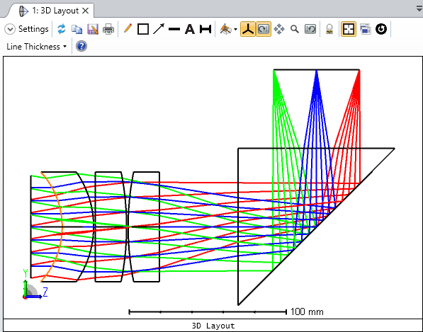
This setup is tricky because the coordinate system that we are starting in before we enter the prism geometry and the coordinate system we end in after leaving the prism are different. One first step we could take is to use the Tilt/Decenter tool to select our surface range encompassing the prism, but due to this change in coordinate systems before and after the prism, the distance from the prism to the image plane won't be preserved:


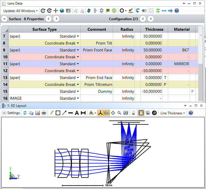
The other note to make is that, again, since the Tilt/Decenter tool pivots about the first surface vertex of the selected range, the prism currently is only able to tilt about the 'Prism Front Face' vertex. To start making this pivot arbitrary, we can use Tilt/Decenter tool to modify the placement of just the 'Prism Tilt' surface, since this will become the pivot point for the scan motion of the prism (like in the slides, I also add in a Dummy surface after and co-located with 'Prism Tilt', and I make the returning Coordinate Break surface in this action also have a Pickup solve to undo the thickness of 'Move Prism Pivot':


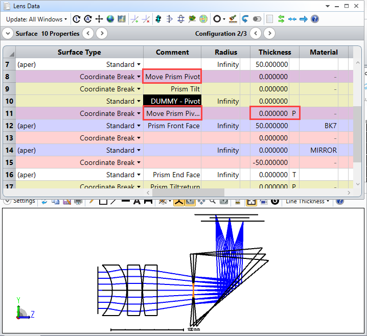
Now, the pivot point can be adjusted, but of course, we still have some work to do after the prism geometry has finished being created:


The problem is that we are breaking the relationship of all surfaces after the 'Prism End Face' to where the end face was placed before any tilting. To fix this, we need to set up our Coordinate Breaks after the 'Prism End Face' surface such that we always arrive at the nominal placement of Prism End Face. I think there are many ways to accomplish this, but the way I took for now was:


 1. Remove the thickness solve on Surface 16 so that it remains fixed at 0mm

 2. Modify Surface 17 so that it now has a Coordinate Return solve to bring us to the same position and orientation as Surface 8, the nominal placement of the Prism Front Face surface

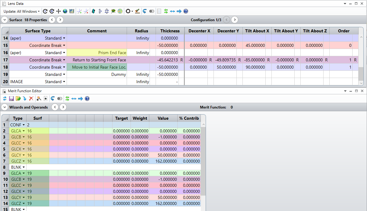
 3. Insert a new surface after Surface 17, make it a Coordinate Break, and define its parameters such that it is at the same position and orientation of the nominal placement of the Prism End Face surface


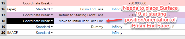
The last step is important, because we'll have to match not just the XYZ location of the Prism End Face nominal point, but it also needs to have it's axes adjusted because we have been folded by the reflection imparted by Surface 14. One way to check that these surfaces have the same position and orientation is with the Merit Function Editor and the GLCX/Y/Z and GLCA/B/C operands (giving us global position and direction cosines, respectively).


Now, the scan motion of the scanning prism is independent of the surfaces following the prism, and the pivot can be placed independently as well:


So, we can really see the how important it is to understand where our surfaces are being defined in Sequential Mode. Because the placement of surfaces depends on the parameters of the surface before it (such as the Thickness of any surface being used, or the Tilt/Decenter parameters of a Coordinate Break), it can be a bit tough to understand the global placements and orientations of any given surface. That said, there are ways to get at this data (merit function operands, the Prescription Data report, etc). Other ways of checking this data are also explored in the articles that Thomas shared previously, so I'd definitely encourage that as some further reading if you haven't gone through them already!


Please feel free to add onto this thread if there are any more questions or if there are additional thoughts/approaches on this setup. I'd be interested to hear other perspectives and techniques that other folks might have developed!


~ Angel

Userlevel 7
Badge +3

This is seriously good stuff Angel and I applaud you for producing such a great set of notes. I do wonder if you (R&D) should add a new tool or upgrade the existing tilt/dec tool to support an arbitrary (x,y,z) rotation point. The existing tool does well if the rotation point is the first surface vertex. But if you want a tilt about somewhere else, it's down to the user to do all this propagate forward/tilt/propagate back/do the hokey-cokey and turn around stuff.


A new tool that tilts/decs surfaces a->b about some defined (x,y,z) would really save users from all this head-scratching 😊 and you've set out the procedure to follow very clearly.

Userlevel 2
Badge

I would really appreciate a tool that allowed rotation about an arbitary (x,y,z) point.  Even better something like in Breault Research's ASAP the command 'ROTATE d ABOUT a, b, c, x, y, z' where d is the rotation angle in degrees and (a, b, c) is an arbitary axis direction vector passing through a point (x,y,z).


Andrew

Userlevel 4
Badge +2

Hi Mark and Andrew,


I agree, and will keep this in mind. 


Thomas

Userlevel 3
Badge

Oh, my, yes, excellent posts by Angel, and great comments by Mark and Andrew.


Please add my vote for tool for an arbitrary rotation about a point.  Is it possible it could even be a single Surface that could be inserted and deleted... instead of a tool like Tilt/Decenter that inserts multiple confusing Coordinate Break surfaces whose individual alterations or deletions can really mess things up?  Or is that a hopelessly naïve suggestion because of how Sequential works?


Meanwhile, may I also recommend Erin Elliott's KnowledgeBase article KA-01344 titled 'How to pivot any element about any point in space':


https://my.zemax.com/en-US/Knowledge-Base/kb-article/?ka=KA-01344


-- Greg

Userlevel 4
Badge +2

Hi Greg, I do believe that having a single surface do all that wouldn't be consistent with how sequential mode works.


It seems we need a certain number of  coordinate breaks to do that, but it could be automated by a tool, or a macro.

Reply