Modeling speckle

  • 17 April 2023
  • 8 replies
  • 812 views

Userlevel 7
Badge +3

Speckle is created by the interference of multiple, mutually coherent optical fields that have random phases at any point on a detection surface.  This could be associated with laser light scattering from a rough surface or from the interference of multiple modes emanating from a multimode fiber.  For multimode fibers, it may be best to use POP in a sequential model in which the beam leaving the fiber is modeled as a coherent superposition of LP (or LG) modes.  Alternatively, we show here how a simple non-sequential ray-based model can be used to simulate speckle arising from rough-surface scattering. 

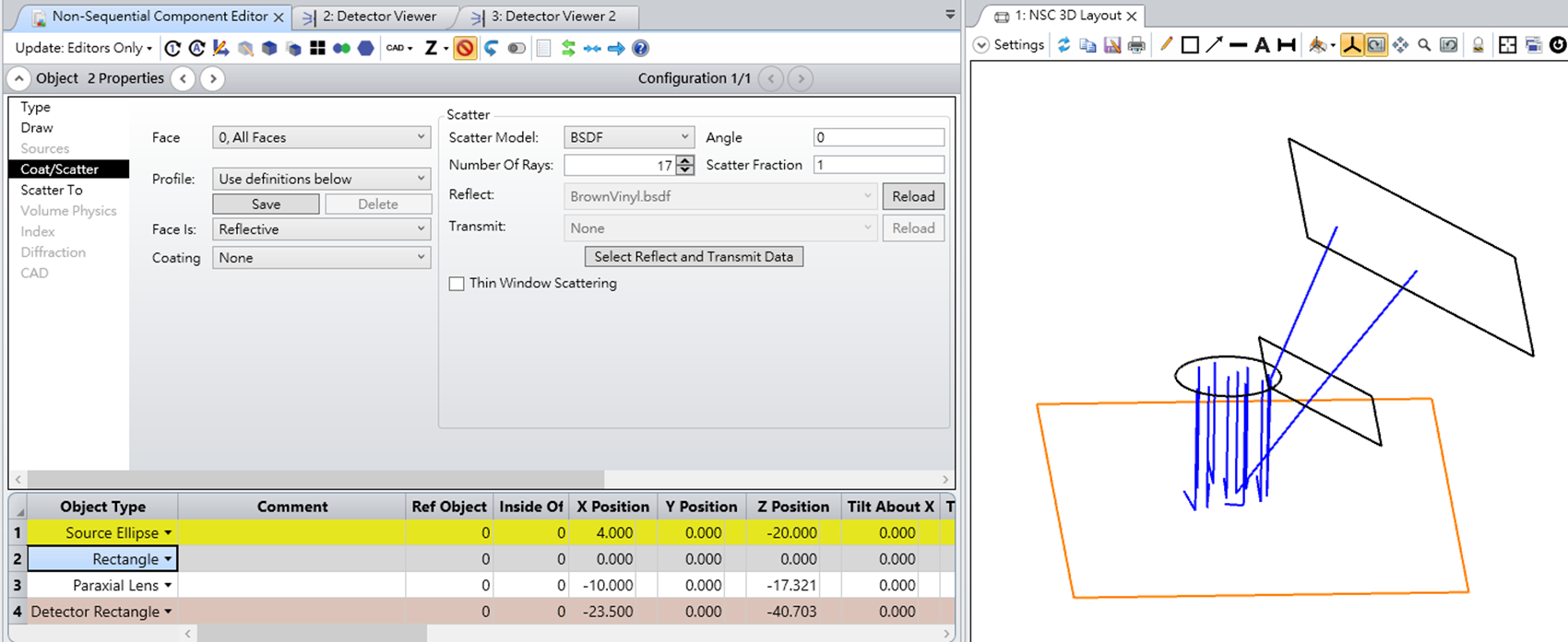
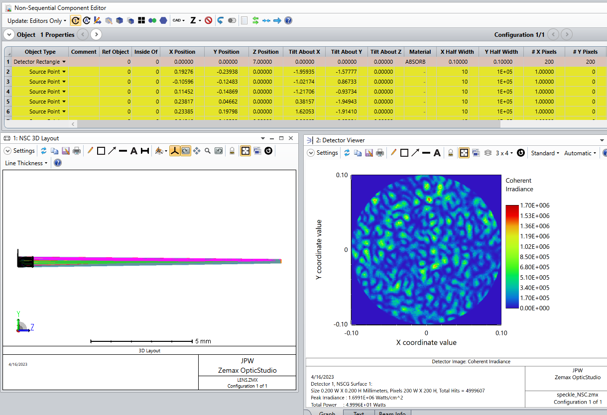
To model light leaving a rough surface, we can employ Huygens’ Principle and use a set of point sources that are randomly phased over (0,2pi).  This assumes the height variations on the surface are large enough to create such a random process.  Ideally, we would use a single non-sequential source that emits rays uniformly over some spatial region and within a defined cone angle.  However, because we want multiple rays leaving any given point to all have the same phase relative to one another, but random with respect to all other points, a reasonable option is to create a discrete set of point sources that are distributed across a planar “illumination region.”  To avoid periodic sampling artifacts, these point sources can be placed randomly within the illumination region.  The point sources then illuminate a Detector Rectangle placed some distance away, with the detector set to display the Coherent Irradiance. 

Because we will be generating speckle patterns that have fine structure, the point sources should have a small cone angle that provides illumination of the detector only over some small region of interest.  Moreover, the point sources should be individually pointed at the center of the detector to maximize the spatial overlap of the beams.  This can be done programmatically using ZOS-API.  If the distance from the point sources to detector changes, then the pointing angles can be readily updated.  A sample Matlab script is attached.  Note that the script can be used initially to create a set of point sources, then afterwards the properties of these point sources (the xy-locations, xy-tilt angles, and cone angle) can be modified as needed without having to recreate the individual sources.

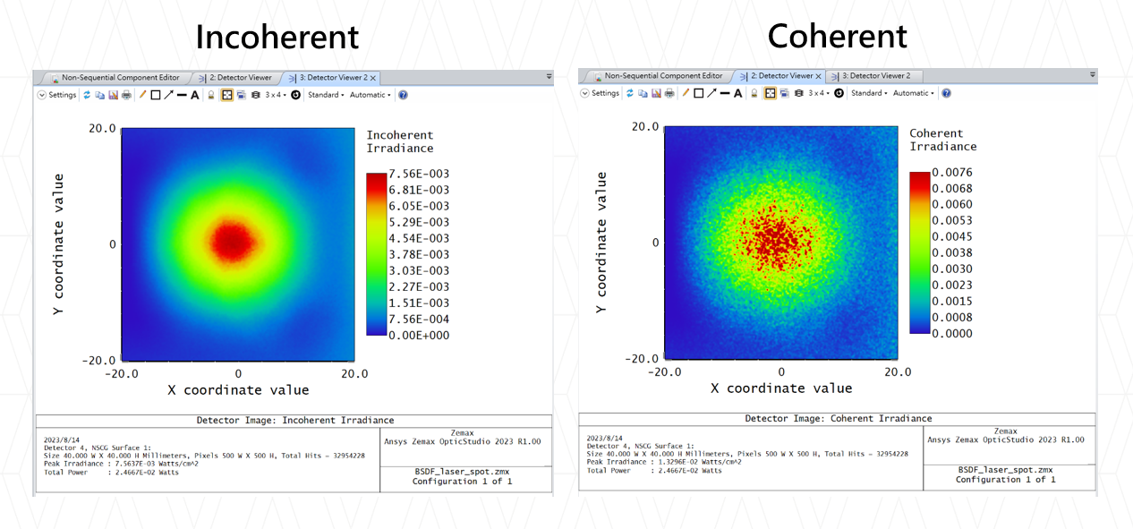
Here is an example in which 50 point sources (0.550 um wavelength) randomly sample a square illumination region that is 0.5 mm x 0.5 mm.  A detector (0.2 mm x 0.2 mm) is placed 7 mm away from the source plane.  Each point source has the same intensity, but a random phase.  A well-defined, fully-developed speckle pattern is observed. 

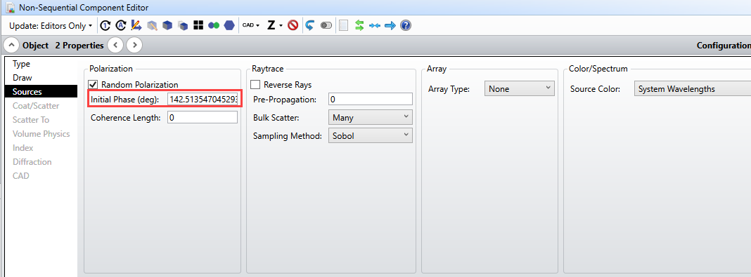
Here is the phase setting for the first point source (which is Object #2 in the NCE).


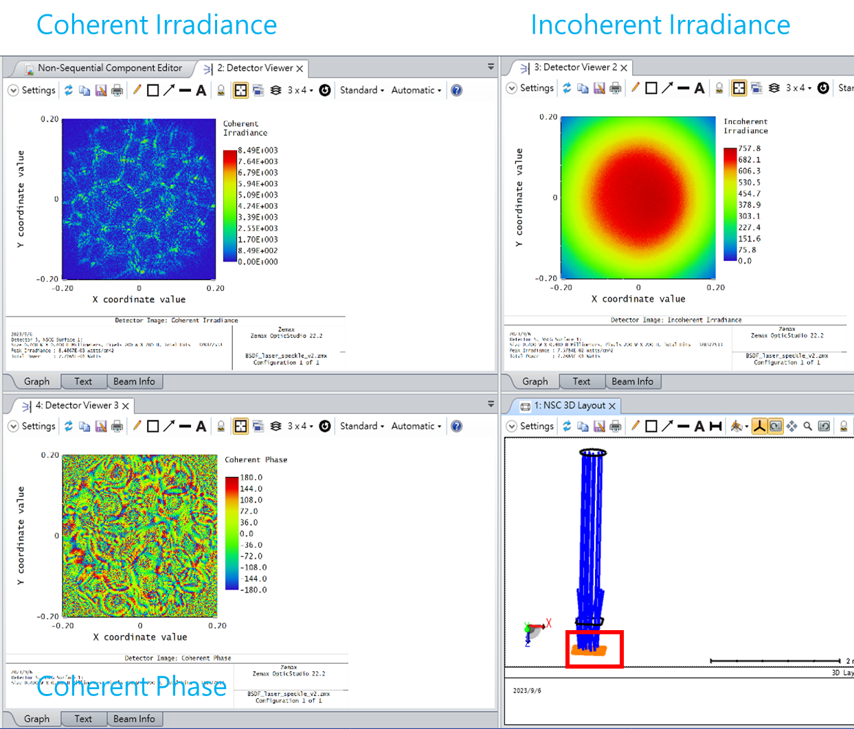
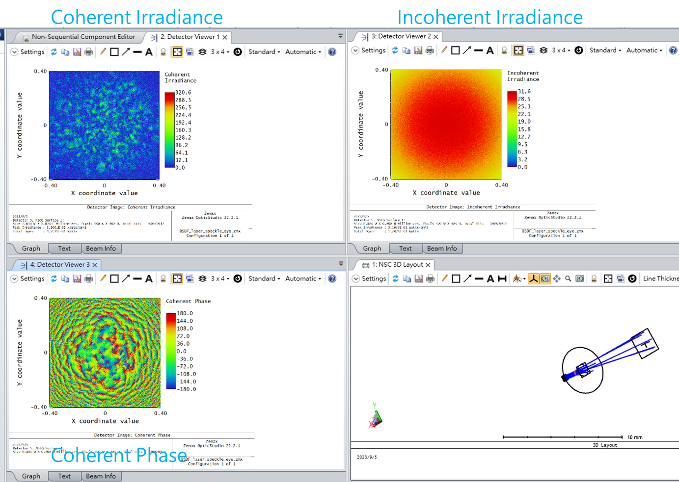
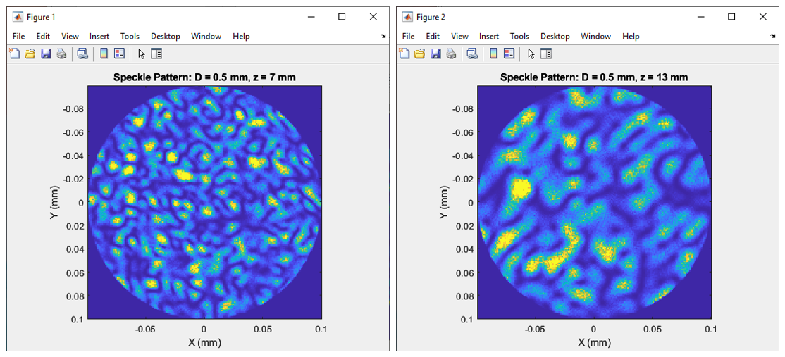
If the propagation distance is increased, the average speckle size should increase proportionately, which is what we find when going from z = 7 mm to 13 mm:


A good reference is Speckle Phenomena in Optics, Theory and Applications, 2nd ed., by J. W. Goodman.  In particular, Chapter 5 discusses the spatial structure of speckle. 

In the model described here, various changes can be made to the relative intensities and phases of the point sources in order to modify the speckle pattern properties.  For example, if the relative phase distribution is not uniform over (0,2pi), as measured from the rays striking any given detection pixel, then the speckle contrast should be reduced so that it is no longer “fully developed.”  Presumably, we could also incorporate imaging lenses or other optical components into the path and see how the speckle changes.

Regards,

Jeff


8 replies

Thank you Jeff for the wonderful post! Out of curiosity, would you happen to know why speckle can’t be modeled using a single (coherent) source ellipse, whereafter the rays are scattered through a rectangular volume before hitting a detector? Does the scattering model inside the volume not account for the phase changes accrued with path length differences from the scatter? Or do the launched rays never actually interfere with each other, as you have manually ensured with the XY tilts in this model?

Thanks again!

Userlevel 7
Badge +3

In volume scattering, each scattering center generates a spherical wave that interferes with the primary incident beam as well as with the other scattered waves.  Therefore, every point on a detection screen sees light from the entire set of scattering centers, which is a very important key point.  For spatially coherent light this leads to speckle formation.

To mimic this using ray tracing would require a very large number of scattered rays to be generated at each scattering location and then subsequently propagated so as to illuminate all detector pixels.  However, in OpticStudio, volume scattering simply involves one incoming ray changing its direction, with the scattered ray’s phase being randomized.  So this approach does not capture the actual physics of the problem. 

In the model I describe above (in my original post), the randomly-phased point sources lie on a plane, but they could just as easily lie within a volume (randomly located) to simulate bulk scattering.  In this case the phase of each point source could be related to its distance from the input surface of the volume.   The random locations would then randomize the relative phases.  So you would end up with a very similar result.

Userlevel 7
Badge +3

Wonderful post Jeff, thank you for taking the time to write this up. - Mark

I used bsdf to build up a easy model for an eye looking at speckle patterns as below :

I think this model can simulate part of random phase from path and rough surface .

Is it enough for an eye looking at speckle patterns ?

If I want to improve the model , are adding several different BSDF surface made by lumerical or splitting the source into several random initial phase sources good ideas?

I would like some advice , thank you.


Userlevel 4
Badge

Hi Jackie,

BSDF is probably not detailed enough (no phase, no spatial dependance). Your grains look small compared to those in the original post. The speckle grain size is due to the aperture of the imaging (your paraxial lens), so there are 2 quick ways to check for validity:

1- change the aperture of the lens, the speckle grain size should change inversely. 

2- If you are using smoothing in the detector viewer and changing the smoothing radius changes the grains size, then you are not seeing speckle but simply numerical noise.

Best regards

Hi Ray,

Really Thanks for your advice ! As you said , only BSDF can’t bring out the phase , so I modified the model .

To bring out the phase , I combined grid sag surface with BSDF . Looks like it works well!

irradiance : 

irradiance + paraxial lens :


Hi Jeff

Thank you for sharing this script. This is excellent!

I do have few questions

You chose 0.5mm and then divided it 50 times so each illumination zone is about 0.05mm or 50ums. At 7mm away the speckle diameter on the detector (or aperture) should be 2.44*530 nm * 7mm/50ums ~ 180ums from a single sub-illumination zone.

The detector you have designed is 200um. So I should expect only one speckle per illumination spot on the detector.

But with 50 illumination spots or 0.5mm diameter source I should expect a speckle size of 18ums or the detector along its length will be packed with ~10 or so speckles.

Do you think that is how the simulation will eventually work out or you expect it to be a bit different the way Zemax calculates it?

Userlevel 7
Badge +3

Hi @rjn 

I don’t quite follow your description of sub-illumination zones.  However, in my model a single point source produces uniform illumination on the observation plane.  Two point sources yields an approximate sinusoidal interference pattern having a period related to the angular separation of the two points as seen from the observation plane.  As more randomly-phased points are included, the speckle pattern develops.  With enough points the result mimics a continuous illumination spot on the scattering surface.

As far as speckle size goes, I refer you to the simple result described in Goodman’s book on speckle (see attached).  For free-space propagation from the scattering surface to the observation plane, the average speckle area (or field correlation area) is simply Ac = (lambda z)^2/A, where lambda is the wavelength, z is the distance between the scattering surface and the observation plane, and A is the illumination spot area on the scattering surface.  The average speckle size is ~ sqrt(Ac).  For the first example in my original post, the numerical values are:  lambda = 0.55 um, z = 7 mm, and A = 0.25 mm^2.  This yields a speckle size of sqrt(Ac) = 7.7 um.

Regards,

Jeff

Reply