Improved default settings for ray tracing with CAD parts - OpticStudio 21.3.2

  • 6 December 2021
  • 1 reply
  • 215 views

Userlevel 3
Badge +2

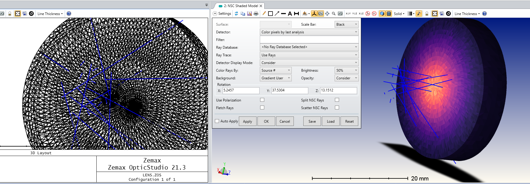
In OpticStudio 21.3.2 we implemented improved default settings for the the faceting used when ray tracing CAD objects using the ACIS libraries.

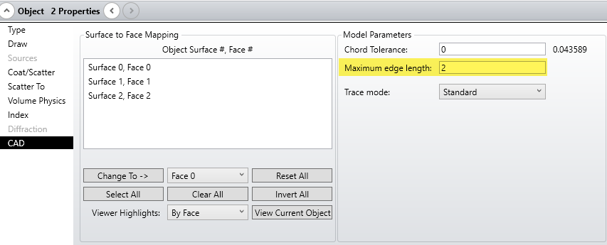
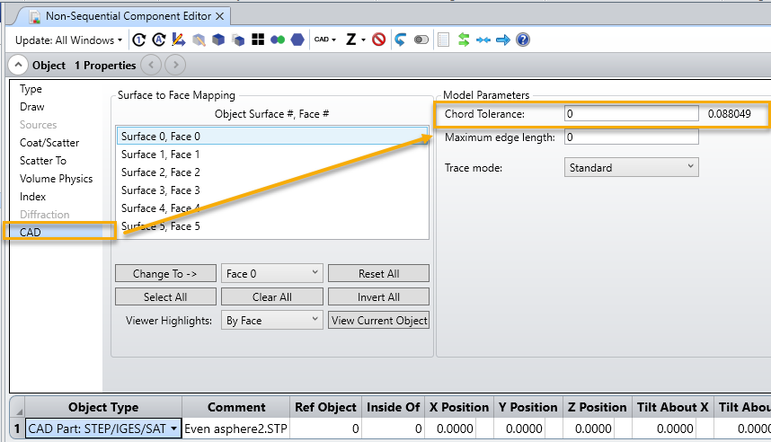
In Object Properties...CAD setting the Chord Tolerance value to 0 will result in OpticStudio will automatically compute a Chord Tolerance related to the size of the CAD object in question. In OpticStudio 21.3.2 this default setting is smaller than in previous releases to enable more accurate ray tracing with default settings in a wider range of circumstances.

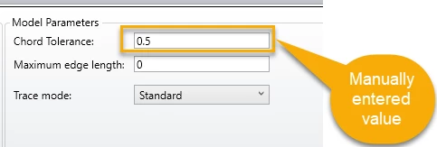
The actual Chord Tolerance used (in lens units) is shown to the right of the setting box. You can find out the more about the Chord Tolerance setting in the Help Files section. The Setup Tab > Editors Group (Setup Tab) > Non-sequential Component Editor > Object Properties (non-sequential component editor) > CAD  


In some cases the more accurate default settings will lead to longer ray trace times, but in this case you still have the flexibility to set the Chord Tolerance manually to a larger value, to produce a coarser faceting which will ray trace faster.

An example of a manually entered Chord Tolerance


1 reply

Userlevel 3
Badge +2

In addition, in OpticStudio 21.3.2 triangular facets used to approximate object shapes in the shaded model and 3D viewer are no longer directly tied to the Chord Tolerance value set in Object Properties, as was previously the case. Instead the Chord Tolerance value in object properties is used for ray tracing, but the value used to generate triangles for the layout windows is now 100 times higher. This allows smaller Chord Tolerance values to be used for accurate ray tracing without affecting the performance of the layout plot by drawing many unnecessary triangles.

If you are using an object as a detector there is the possibility that the triangles automatically generated for visualisation are too large to provide the resolution you need.

Low resolution pixels on detector object

In this case you can make them smaller and more regular by modifying the Object Properties > CAD > Maximum edge length setting to a non-zero value.

This will produce a higher resolution detector without affecting the ray tracing speed and accuracy.

Higher resolution pixels on detector object


Reply