How to model a birefringent polarization rotator?

  • 8 December 2020
  • 3 replies
  • 993 views

Userlevel 5
Badge +2

In order to properly model the polarization rotation of an object made of birefringent material, we have to set up the ray trace mode of the object in the Non-Sequential Component Editor under Object Properties > Index > Birefringent type > Mode:


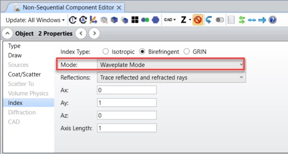
The Mode control allows selection of which rays are actually traced. The distribution of energy does not change with this setting, and energy assigned to rays that are not traced are placed in the “lost energy (thresholds)” sum. Either ordinary or extraordinary rays, or both, may be traced. Waveplate Mode traces the energy along the path of the ordinary ray, however, the extraordinary electric field is also propagated with the ray, and the total electric field will be phase rotated by the differential index in the ordinary and extraordinary directions.


Waveplate mode has to be used to model the polarization rotation of the object.


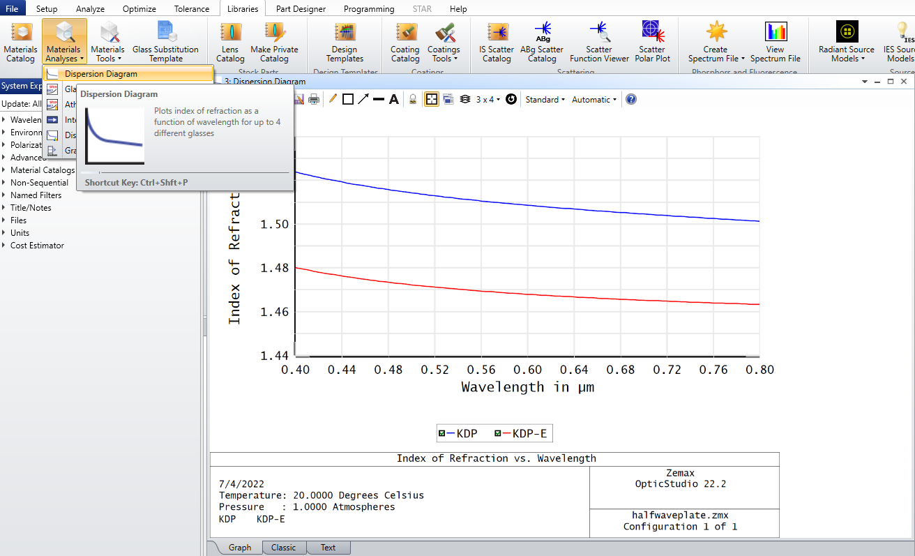
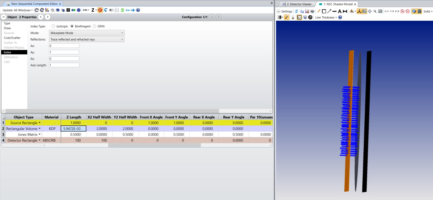
In the attached example file, an extended source (Source Rectangle) launches rays parallel to the z-axis with polarization [1, 1]. Then, a Rectangular Volume with birefringent material KDP is used as a half-wave plate -- the thickness of the object is set up, so that the optical path difference between the ordinary and the extraordinary rays equals the half of the wavelength. The half-wave plate rotates the polarization by 90 degrees. Finally, a Jones matrix object is used to check the resulting polarization -- it is set to transmit polarization parallel to the source polarization, so it blocks all the rays:


Further information about the Birefringent Types settings can be found in the Help file at:


The Setup Tab > Editors Group (Setup Tab) > Non-sequential Component Editor > Object Properties (non-sequential component editor) > Index > Birefringent Types


3 replies

Hi Csilla, how did you calculate the thickness of your KDP component? I used Sellmeier's formulas to get the ordinary and extraordinary indices for KDP at the 500nm wavelength you used. I then used the following formula to obtain the thickness: PHI=(2*PI()*e*(ne-no))/lambda. PHI is the phase difference between the ordinary and extraordinary axis of the waveplate, which is PI() in the case of a half waveplate and PI()/2 in the case of a quarter waveplate. e is the thickness, ne is the extraordinary index (from the previous Sellmeier application), and no is the ordinary index (also from the previous Sellmeier application). I can't get the same value of 5.94E-3 you got. My goal is to be able to model a quarter waveplate and a half waveplate in non sequential mode

Best regards,

Marie.

Userlevel 5
Badge +2

Hi @Marie.Fournier ,

Thanks for your question here.

I think the equations you used are correct, I used the same equations in my calculations.
That means for a half-wave plate the phase difference is PHI=PI()=(2*PI()*e*(no-ne))/lambda, so the thickness equals e=lambda/(2*(no-ne)). Similarly, for a quarter-wave plate the phase difference is PHI=PI()/2=(2*PI()*e*(no-ne))/lambda, so the thickness equals e=lambda/(4*(no-ne)).

As for the refractive indices, I used the built-in Dispersion Diagram tool under Libraries > Material Analyses to determine the no and ne indices:

You can find the numerical values in the Text tab of the analysis. Based on this, no=1.514 and ne=1.472. I double-checked and I got the same refractive indices using the Sellmeier 1 formula and the coefficients reported for KDP and KDP-E in the built-in Birefringent.AGF catalog.

I hope this helps, but if you have any further questions, please ask.

Best,
Csilla

Hello Csilla, thanks a lot!

I didn’t know that the built-in Dispersion Diagram existed.

Now it will be easier.

Best regards,

Marie.

Reply