To define an acceptance angle, you may use filter strings or define a table coating. For the first one, you can use the following filter strings:


The Setup Tab > Editors Group (Setup Tab) > Non-sequential Component Editor > Non-sequential Overview > The Filter String


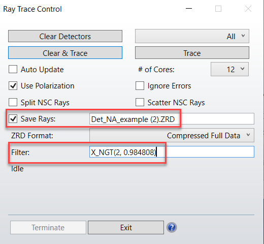
So for example, if you want to select only rays incident at an angle of less than 10 (cos(10) = 0.984808) degrees on your detector (Object 2 in this case) whose normal vector points along local +z, the filter string would be:


X_NGT(2, 0.984808)


When running the ray trace, you can define this filter and save the ray data: this means that only if the ray passes the filter, it will be saved:


After that, you can use this ray database for your analysis.


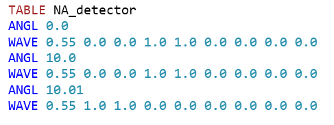
The second possibility would be define a table coating and apply it in an object placed in front of the detector. With this coating format the transmission and reflection may be defined as a function of incident angle and wavelength. To read a complete description of this kind of coatings, please, browse the help files as such:


The Libraries Tab > Coatings Group > Defining Coatings > The TABLE Data Section


So the same acceptance angle (less than 10) could be achieved with a coating like this:


This forum really needs a LIKE button for useful posts 😁


I think another way is to define the angle x, y minimum and maximum in the NSCEditor to the range you want. Then only data in the range you want will be saved. 

I agree about the Like button --  I often see posts I like but all I can do is nod my head.  ;-)


I have used both methods to limit the acceptance angle of a detector. They are both useful. But, unless I am mistaken, they are not equivalent. The filter string solution restricts rays to be within a cone of acceptance aligned with the local Z axis. The min/max of x and y angles is not axially symmetric about the Z axis.


Kind regards,


David


Hi guys, 


You'll be happy to hear that a 'Like' button (along with several other things) are in the works. Stay tuned in the coming weeks for some updates to the forums! 


Cheers,


Nick


P.S. I agree, great post, Berta!

Hi guys!


Any optimization operand that can find the amount of power within a cone of acceptance of detector ?


You could try using the Table Coating approach described above, which allows the user to put an angular filter in front of the detector, and then use the NSDD operand to find the detected power.


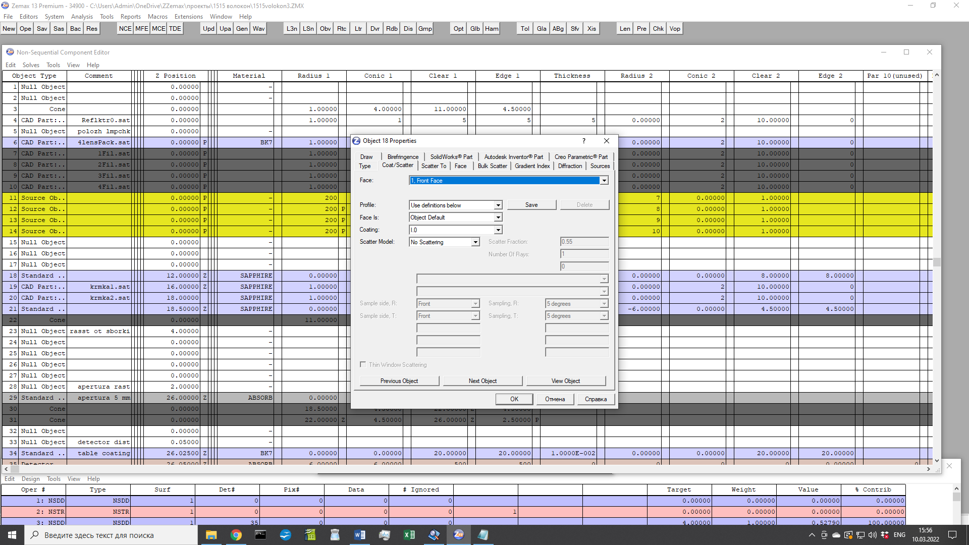
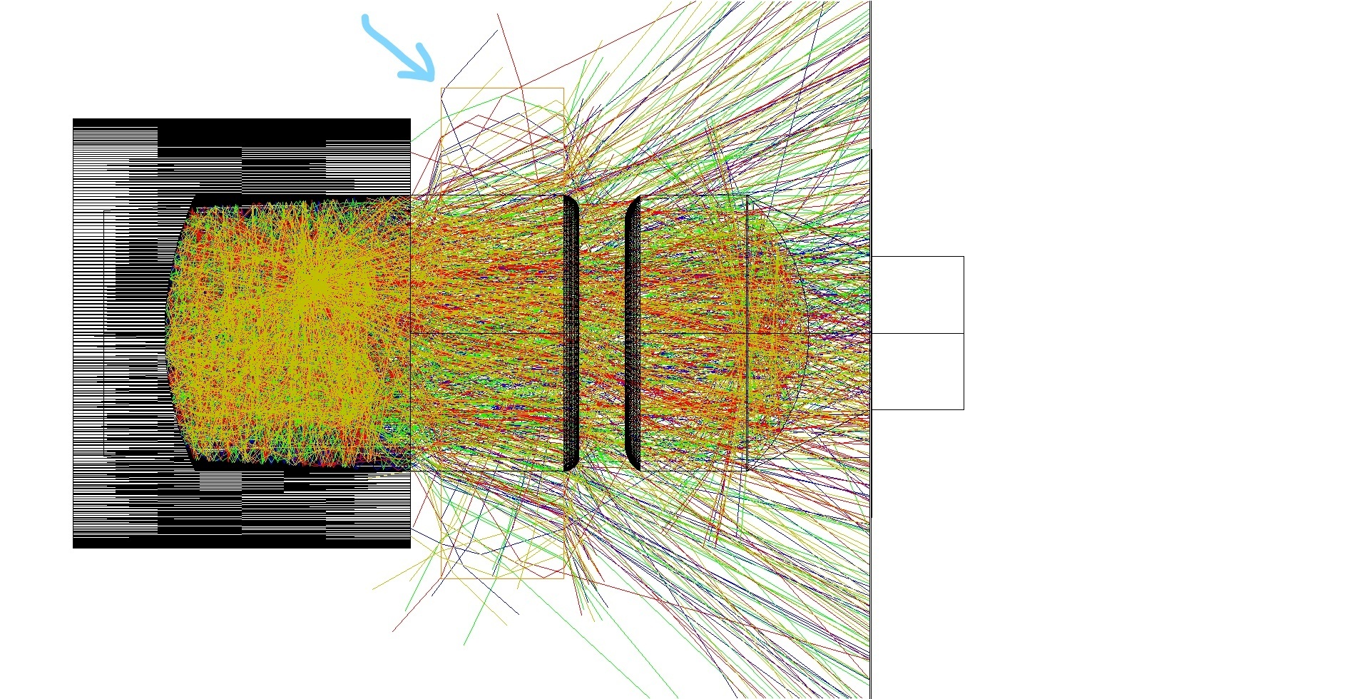
I tryed to apply coatings on the face of nonsequential element (face 1 Standart lense) but nothing changed in comparison of non coating case. I apllied I.0 coating to face 1 of 18 Standart lense after which rays have to reflect from Face 1, but they goes through. The Face 1 is marked by arrow in picture below. 

What I did wrong ?


I find the answer why choosed coating doesnt work)

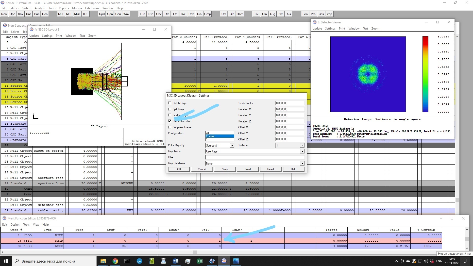
To work with coating the polarization option have to be choosed like showed with arrow below:


Dear colleagues!


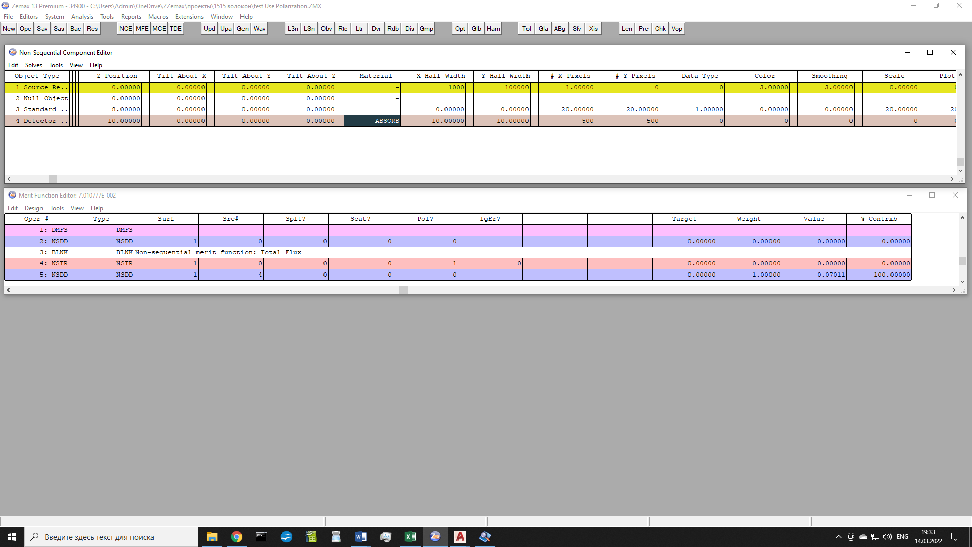
In NSC mode if I choose to take into account a polarization (pol? in Merit function NSTR or Use Polarization in Ray Trace ) my detector gets significantly less total flux then without polarization. Thats only happen if between source and detector is some other element. In picture below such element is 3 Standart Lense (but in that case it havent any material, so rays have to go through it without of any disturbance). 

Why the polarization on option in that case (empty 3 Standart Lense) impacts the total flux on detector ?


The dicrepancy between total flux for “Use polarization” on in Ray Trace and off disappeared. If the 3 Standart lense have empty material the total flux doesnt depend on polarizaton. It dissapered after I some times cleared and make again the 3 Standart lense. Rather it was some programm error.


Early as can be seen from figure above Merit editor the total flux is 0.07 (Pol? =1). Without of polarization (Pol?=0) the total flux was 0.5.


Reply