Are you choosing a physical stop?

  • 29 July 2022
  • 8 replies
  • 2436 views

Userlevel 2
Badge

An interesting problem has surfaced as the Zemax team at Ansys continues to develop toolsets to aid the simulation of small form-factor, wide-angle systems such as cellphone camera lenses. Different ways exist to set up and model a stop with a lens traversing its aperture, but which is the best way? With this post, we share our recommendations and seek your feedback based on your experiences tackling this challenge.

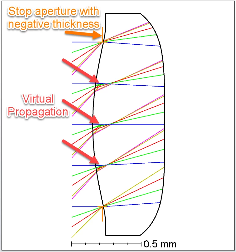
Virtual propagation modeling is one of the ways to model these stops. Technically, the portion of the lens that goes through the stop will modify the wavefront before the stop limits the wavefront with its clear aperture. Therefore, we cannot use virtual propagation to model these stops because we will be adding non-real pupil aberrations to our optical systems since we are forcing the entrance pupil to be flat when it is not.

Here is an example of a stop with a lens going through it.

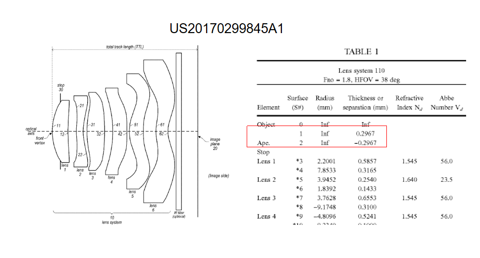
By definition, “the aperture stop is the aperture in the system that limits the bundle of light that propagates through the system from the axial object point. The stop can be one of the lens apertures or a separate aperture placed in the system. However, the stop is always a physical surface.” (Field guide to geometrical optics, J. E. Greivenkamp).

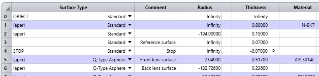
Therefore, a team of Zemax Engineers at Ansys has studied the effects of modeling the stop in different ways and concluded that the best way to model these systems is by separating the lens into two: the first section that goes through the stop and the section that does not go through the stop. These “two” lenses will embed the stop as shown below.

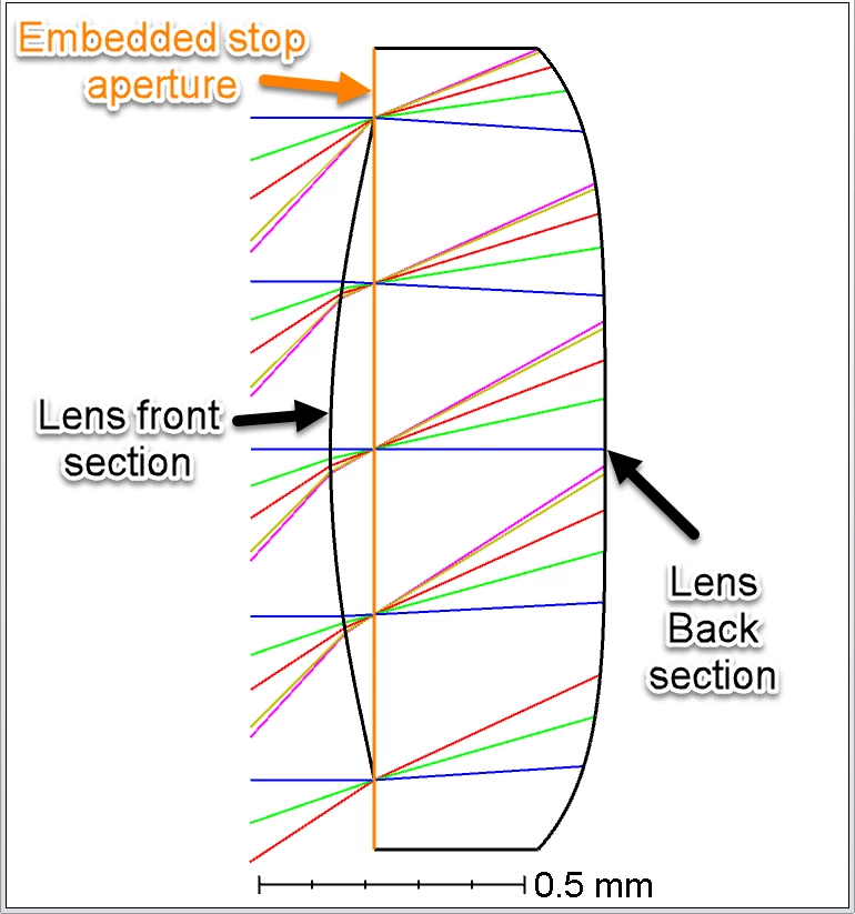
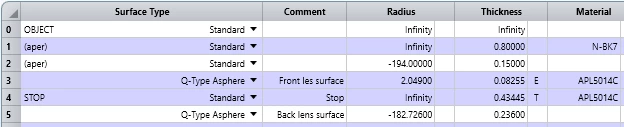
The main benefit of modeling the stop in such a way is that the rays do not experience negative propagation, and the stop becomes physical since the entrance pupil is now the correct image of the stop. Additional benefits are that OpticStudio will now be able to sample the pupil uniformly, avoid unnecessary vignetted rays, and make better use of our recently enhanced ray aiming capabilities.

Note that the first curved surface can also be used as the stop, but the Huygens-Fresnel principle indicates that this is not a physical solution either.

While embedding the stop is our recommendation, we want to hear from our users. What do you think? Are you choosing a physical stop?


8 replies

Userlevel 1
Badge

Hello guys,

     Check the Apple patent.

@David.Vega David, looks Apple guys use the virtual propagation method. any disadvantages involved?

Userlevel 7
Badge +3

I can’t speak to the Huygens-Fresnel part of the question as I don’t really follow that bit myself. But I think I would focus on: is there really a surface that defines which rays pass through the system and which don’t?

For example, a He-Ne laser interacting with a lens which is much bigger than the 1/e^2 width of the laser really doesn’t have a stop surface, as the energy in the beam has effectively gone to zero before it hits a limiting aperture.

Assuming there really is a surface whose edges are illuminated by the light that doesn’t get through the system, then this is important for diffraction calculations. The pupils, being images of the stop, are the only places where the wavefront has a sharp edge and can be considered ‘free of diffraction’. That’s why the FFT and Huygens PSFs work so well: you get the wavefront at the exit pupil and can then assume that the only significant diffraction is the propagation from the XP to the image. This is sometimes called the ‘single step’ approximation.

If that assumption is not good enough, then give up on the pupils altogether and use POP. That goes surface by surface, so requires high sampling on highly aberrating surfaces, but lets the beam interact one surface at a time with whatever combination of surfaces and apertures there are. As I said in an earlier reply, getting the Lumerical team to verify the Zemax result (or not) would be cool, as their (and other people’s) FTDT code is the only thing I can think of that is superior to POP. But it will take ages to find whatever difference you’re looking for.

  • Mark
Userlevel 6
Badge +2

Hi @David.Vega & @Mark.Nicholson,

This topic has recently piqued my interest again.  I want to try to understand an “embedded” Stop better.  First, a general Stop has 3 main characteristics:

  1. The Entrance Pupil does not matter if you use Float By Stop Size, which is the only “physical” representation of the ray bundle.
  2. Locates the position of the Exit Pupil based on the parabasal Chief Rays.
  3. Locates the diameter of the Exit Pupil based on the Marginal Rays.

For the position of the XP, the parabasal ray trace difference between the “virtual” vs the “embedded” Stop would be miniscule (especially for an “as-built” system where if the Stop isn’t an independent surface, you would try to place it on the least powered surface so the whole lens would be less susceptible to tolerance errors).  

As for the diameter of the XP, the “virtual” Stop accurately calculates the limiting rays for the system, just like the “embedded” system does.  So the size of the XP is the same between the two.

Also, you mention:

Note that the first curved surface can also be used as the stop, but the Huygens-Fresnel principle indicates that this is not a physical solution either.

Can you elaborate on this a little more?  How does this violate the Huygens-Fresnel principle?  This is a diffraction principle, right?  And defining the Stop is in “intermediate” space before we get to “image” space where we need to apply Free Space Diffraction principles.  So, as long as you can accurately locate the Exit Pupil with either the “virtual” or the “embedded” Stop methods, the Huygens diffraction algorithm should remain the same.

Userlevel 2
Badge

Hi Mark, 

Thanks for the update. I do agree pupil display and location should improve. We are actively working on that topic :) and will get everyone updated when we have information to share. I also agree the reverse element tool needs an improvement now that these systems are more common. 

David

Userlevel 7
Badge +3

Hi again David,

Thinking about this some more, for wide angle lenses I think the pupil modeling should also be looked at for wide-angle lenses like these cellphone camera lenses.

As you know, a lens is classed as ‘wide angle’ when the pupil shifts and rotates to accommodate the field of view. But OS, and AFAIK every lens design program, tends to hide that from the user, and presents pupils as being only defined on-axis at the primary wavelength.

The recent updates to ray aiming greatly improved OS in this regard, but there are still no tools for visualizing pupil shift and rotation. I wrote about this here, and  @Michael Cheng wrote a macro that works on a one-field-per-config basis to demonstrate pupil shift. It would be great to see that pupil shift explicitly calculated and graphed as per the graphic in the post I linked to.

It’s also very useful to design wide-angle systems in reverse, like wide-angle projectors, as the ray-aiming is much easier in the reverse direction. We have the ‘Reverse Element’ tool, but it needs to be extended to ‘Reverse System’ to change the field type as well as including the object surface. This alone would make Wide Angle lenses much easier to optimize. Add in the pupil modeling and there would be a capacity unmatched by any code.

Just my 10c,

  • Mark
Userlevel 7
Badge +3

Hi David,

I can’t believe that a propagation over such a short distance would make any difference, but to be super sure, you can use a second dummy surface. Now the prescription would be

Propagate to the vertex of the refractive surface, and place a dummy surface A there. (This is actually the ‘second’ dummy surface.)

Propagate to dummy surface B, located at the Stop. Truncate the beam here

Virtual propagate back to A

Continue the POP from this surface.

On the propagation from A to B and back to A, select ‘Use rays for propagation’ so you don’t do unnecessary POP calculations.

It would be interesting to compare the result with Lumerical’s FTDT code. The Lumerical code will take an age of the Earth to work with such a large beam, but it would be the definitive answer.

  • Mark
Userlevel 2
Badge

Hi Mark,

It is really good to read from you, and thanks for your feedback. I have a question. If you propagate to the stop surface and then make the dummy propagation, have you check if it affects POP results? I am wondering if clipping the beam before the wavefront deformation will affect the results.

David

Userlevel 7
Badge +3

Hi David,

This is a great question and probably deserves to be a KB article.

The problem arises because the Stop clips the beam at the edge, but we position everything with reference to the surface vertex. In OpticStudio, you need a dummy surface for the Stop so you can locate it relative to the surface vertex of the powered surface. In CodeV I think they let you define a delta-z that does the same thing.

The first question is what the stop surface actually is. If it is a lens surface, is it a mount, whatever. The real stop surface might even be in a different sub-system, in which case you treat a pupil as if it were the stop. 

Once that’s clear, my procedure is:

Trace to the Stop surface.

Then do a dummy propagation to the lens surface vertex, and interact with the powered surface.

The dummy propagation does no harm. The only problem is making the length of the dummy propagation equal to the edge thickness, so use an edge thickness solve for this.

As far as I know, this works 100%, and I’d be interested in any cases where it doesn’t. The acid test is to set up a system in pure NS with a point source, an annulus and a lens object. Set the source  so it overfils the annulus and find the first ray that clears the annulus. You should get the same real ray trace results as the sequential model.

  • Mark

Reply