July 12, 2023
1 Tools, Features, and Capabilities
1.1 Creo Parametric 8 & 9
OpticsBuilder is now supported on PTC Creo Parametric 8 & 9
OpticsBuilder is now fully supported on PTC Creo Parametric 8 and 9. Users can expect the same functionality found on OpticsBuilder for Creo 4, 5, 6, and 7.
Please note that Ansys Zemax OpticsBuilder 2023 R2 is the final release of Creo 4.
1.2 Fold Mirror Tool - New Features
Fold your system to fit within tight, space-constrained assemblies.
A legacy tool with new updates, the Fold Mirror Tool offers users a way to simulate their environment and place fold mirrors that allow their optical product to fit in tight space-constraints. This important update adds greater additional functionality to the Fold Mirror Tool.
Fold Mirror Tool improvements include:
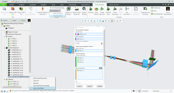
- Fold-mirrors can now be edited once placed in the system.
- If an undo is needed, it can be accessed by right-clicking on the Fold Mirror in OpticsBuilder’s Optics Manager.
- A fold mirror may be placed between optical components and a detector by selecting the detector as both the second reference and the target component.
- Users may rotate a source with a fold mirror by selecting a source as both the second reference and the target component.

1.3 New Component Support
Nonsequential Extended Polynomial with User-Defined Aperture
OpticsBuilder will support OpticStudio’s Sequential extended polynomial surface with a Nonsequential Extended Polynomial object with user-defined aperture. OpticsBuilder will import this new component type using a STEP import.
2 Libraries and Catalogs
2.1 ISX Scatter Libraries
ISX scatter libraries are now removed from OpticsBuilder
The ISX scatter libraries have been removed from Ansys Zemax OpticsBuilder 2023 R2, as these libraries rely on obsolete Microsoft components that could potentially introduce IT or security vulnerabilities in the future. Any designs utilizing .isx scatter libraries will need to be converted to use the .bsdf scatter libraries.
2.2 Parasolid CAD Libraries
Parasolid CAD libraries are now in use
OpticsBuilder now utilizes Parasolid CAD libraries to create faster and more accurate optical geometry. This aligns with the new Parasolid support found in OpticStudio and existing Parasolid support within Ansys Speos.
2.3 Dictionaries & Tagging
New tracking introduced between OpticStudio and OpticsBuilder
OpticsBuilder incorporated a new feature that occurs behind the scenes called Dictionaries & Tagging. This functionality assists the transfer of data between OpticStudio and OpticsBuilder in order for both products to better track objects and data as they export, transfer, and import between the two products. Users will not see any obvious changes but will overall have a better experience when sharing files.
3 Bug Fixes
Ansys Zemax OpticsBuilder 2023 R2 includes the following bug fixes:
- Crashing -
- Creo was crashing when OpticsBuilder was deactivated and reactivated through Creo’s Tools > Auxiliary Applications.
- In Creo 8.0.7.0, the preview function when adding a detector volume would cause Creo to crash.
- Import ZBD File -
- Sometimes while Import ZBD File was loading a file, a second window would appear with a message such as a component having zero thickness. This window would open in the background, and it would appear Creo was hanging.
- The Biconic lens object type would give an error during Import ZBD File. It would also appear with some features missing.
- The Boolean Native object type was scaling incorrectly during the Import ZBD File process.
- During Import ZBD File, the sample file “Cellphone Camera Lens EndDesign.ZBD” was scaling incorrectly to Creo’s graphics area.
- If a user changed the system units in OpticStudio and then prepared a file for OpticsBuilder,, the file would import with the coefficients showing different system units in the OpticsBuilder Optical Properties compared to the Creo Properties menu.
- Equation-Driven Import -
- The Off-Axis Mirror object was not importing with correct geometry with the “Equation-Driven” import option turned on.
- If a customer was using their own custom part templates, Equation-Driven Import would not load their file.
- A regeneration error from Creo was showing after Import ZBD File when importing the sample file “ProjectorOS End Design.zbd” with Equation-Driven Import turned on.
- A file that was imported using Equation-Driven Import option could fail if a user attempted to make several modifications using the Mounting Edge tool.
- Update ZBD File -
- During Update ZBD File, for a file with multiple configurations it was possible to select all configurations. This would then stall OpticsBuilder.
- A suppressed component would un-suppress during Update ZBD File.
- If a user changed an optical component’s parameters (I.e., a radius of curvature) and exported this to OpticStudio, the parameter change transferred. If the user Updated the .ZBD file, the parameter change remained. If the user then exported this updated file to OpticStudio, OpticStudio would load the original parameter and did not recognize the change.
- There was a discrepancy between the units used in the component window compared to what was shown in the Update ZBD File comparison table.
- Export ZBD File -
- OpticsBuilder was giving an error message after an attempt to Export ZBD File if mechanical features were suppressed in the file.
- Some mechanical components were being exported at STEP parts when a user chose to Export ZBD File using CAD Part: Creo.
- If a user Exported ZBD File using STEP, then reimported the file and applied a scatter profile to the STEP part, the new Export ZBD File did not retain the applied scatter profile.
- If a user set a flag on a mechanical component as “Rays Ignore” during Simulation, and then Export ZBD File, this flag was not maintained in the exported file.
- The “Save mechanical component as (STEP, CAD Part)” was active during the Export .ZBD File process which would cause an interruption to the export. Once a user chooses “Save mechanical component as” and said “Save”, this option should be disabled so as not to interrupt the export process.
- If a user made a modification to an optical component using the CAD tools, this component reclassifies as an “optomechanical” component. During Export .ZBD File, the coating applied to this optomechanical component was lost when it should have been saved and maintained on the component.
- When selecting “Trace mechanical components as a single part” option in the Advanced Settings, an Exported ZBD File would not include some mechanical components.
- Fold Mirror Tool –
- The Ray Footprint boundaries were not appearing after a fold mirror, in some cases.
- It was not possible to set the fold mirror thickness to less than 1 by using the keyboard. Users could only set this value to less than 1 by clicking the down arrow in the window.
- Optical Component Properties -
- For read-only systems, it was not possible to view the scatter settings in the Optical Component Properties window.
- The material catalogs were not listed in alphabetical order in the drop-down menu in the Optical Component Properties window. They should be listed in alphabetical order just like OpticStudio does.
- After opening and closing the Optical Component Properties window, the mechanical components appearance changed in the Creo graphics area.
- When a user opened the Optical Component Properties window > Coat/Scatter page, a scatter model was automatically being assigned to an unselected lens surface when a scatter model was selected but no faces were in the “Include” list.
- Coat/Scatter settings were partially hidden when a component was activated in Creo Assembly Mode or if a component was opened in Creo Part Mode.
- For an optical component that is imported with a defined scatter model, it was not possible to enable “Thin Window Scattering” in the Optical Components Properties window.
- When attempting to change the front radius of a Biconic Zernike Lens via the Optical Component Properties window, the change would not take effect.
- Generate Lens Drawings -
- In the Generate Lens Drawing tool, some parameters for cemented objects were present in drawings for singlets.
- The roughness symbol position was incorrect for quadruplet assembly drawings in the Generate Lens Drawing tool.
- The Generate Lens Drawing tool had insufficient data to cover more than one cemented object in an optical assembly drawing.
- Miscellaneous -
- After the lens units of an optical component were changed, it converted to an optomechanical component and was removed from the list of considered components during Simulation. Changing lens units should not change an optical components status and it should not remove it from the Simulation list.
- The Simulation was failing for the sample file “Laser Induced Thermal Lensing Effect”.
- The message “All optical components are included” was presented in the Region of Interest tool window regardless of if all optical components were included in the analysis.
- The System Settings window had overlapping areas in the Japanese localized version.
- In a system with all mechanical components suppressed, the Detector Viewer was still outputting data as if the mechanical components were included in the Simulation.
- If a new material catalog was introduced in OpticStudio and assigned to optical components before preparing a .ZBD file for OpticsBuilder, the new materials did not import with the ZBD file into OpticsBuilder and an error message would show.


