Hello everyone, I have difficulty doing Speckle Image simulation of Laser Source.
The laser I use is 266nm DPSS Laser, and the C.L. is about 8mm.
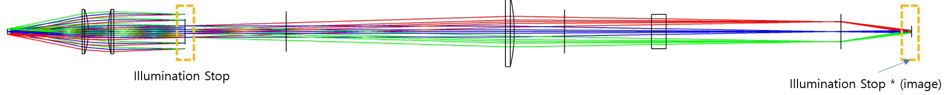
My purpose is to remove Speckle by making each core length of Multi-mode fiber bundle longer than Coherence length, and to know the minimum core length, I would like to perform Speckle Image simulation at Illumination STOP according to the each core length. (Specle image simulation when sampling at least two cores)
The fiber I use is 200um core size, and the total core size of the bundle is about 6mm. How can I simulate the speckle image in this situation?
So far, I've tried... I change this design to non-sequential, set the coherence length of the source to 8mm, and change the z-position of each source (for example, -10mm..). Next, I checked 'coherent iradiance' by placing the detector in Illumination stop position, but there was no difference. If you have any ideas, please let me know.
[Mod note: moved to more appropriate forum for OS-related discussions.]
Best answer by Jeff.Wilde
@david.kwon
I think you have the right idea conceptually, but unfortunately I don’t think your approach will work in non-sequential OpticStudio. Let me explain. First, speckle is created via a superposition of randomly phased waves, e.g., when reflecting a collimated laser beam from a scattering surface, and viewing the light on an observation screen placed some distance away from the scattering surface. In this case, each point on the scattering surface can be thought of as a randomly-phased point source. Duplicating this with rays in non-sequential OpticStudio requires a random phase surface (say using a custom Grid Sag Surface). That’s the easy part.
If you then apply a non-zero Coherence Length to the source, all you will be doing is creating more randomness to the phase of the rays. The Detector Rectangle will still calculate a coherent superposition of all the rays landing on any given pixel, and the speckle pattern will remain. In fact, the contrast of the speckle pattern may actually increase. This is opposite of what you want. To model temporal coherence correctly, the rays would have to be combined differently, in a much more complicated fashion that transitions from fully coherent to fully incoherent as the relative path differences between rays increases. The way OpticStudio implements temporal coherence is based on a very simple (non-physical) approach that only provides a crude approximation in certain cases, such as a reduction in fringe pattern visibility that is accompanied by the presence of a speckle pattern.
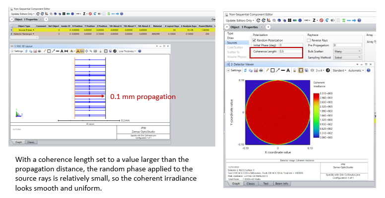
Here is a very simple example to illustrate. It’s just a collimated beam falling on a Detector Rectangle. With a coherence length set to a value that is larger than the propagation distance, the coherent irradiance is uniform as expected:
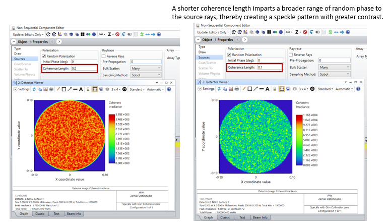
However, upon reducing the coherence length, speckle arises simply because the random phasing that OpticStudio applies is becoming more significant. The contrast of the speckle pattern therefore increases as the coherence length decreases -- again, this is simply a result of the non-physical way that OpticStudio implements coherence. In reality, the speckle should only diminish as the temporal coherence goes down.
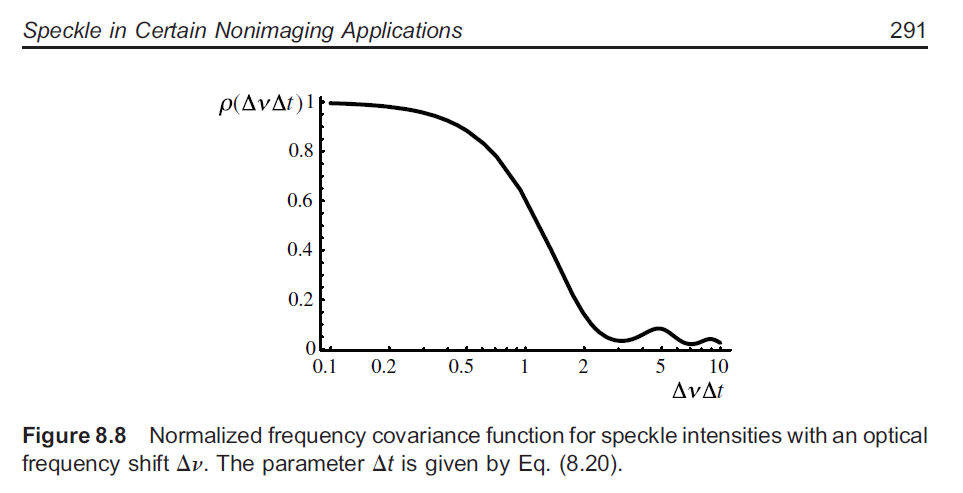
Hope this makes sense. For your problem, I think if you calculate the modal time dispersion of your fiber (i.e., the temporal width of the impulse response) and make sure that it exceeds one over the bandwidth of your source (i.e., the coherence time of your source) by at least of factor of 2 or more, then you may be able to mitigate speckle. See Goodman, Speckle Phenomena in Optics, 2nd ed., Fig. 8.8 which essentially shows how the speckle contrast falls off as a function of the product of source bandwidth and modal delay time for a step-index fiber.
I think you have the right idea conceptually, but unfortunately I don’t think your approach will work in non-sequential OpticStudio. Let me explain. First, speckle is created via a superposition of randomly phased waves, e.g., when reflecting a collimated laser beam from a scattering surface, and viewing the light on an observation screen placed some distance away from the scattering surface. In this case, each point on the scattering surface can be thought of as a randomly-phased point source. Duplicating this with rays in non-sequential OpticStudio requires a random phase surface (say using a custom Grid Sag Surface). That’s the easy part.
If you then apply a non-zero Coherence Length to the source, all you will be doing is creating more randomness to the phase of the rays. The Detector Rectangle will still calculate a coherent superposition of all the rays landing on any given pixel, and the speckle pattern will remain. In fact, the contrast of the speckle pattern may actually increase. This is opposite of what you want. To model temporal coherence correctly, the rays would have to be combined differently, in a much more complicated fashion that transitions from fully coherent to fully incoherent as the relative path differences between rays increases. The way OpticStudio implements temporal coherence is based on a very simple (non-physical) approach that only provides a crude approximation in certain cases, such as a reduction in fringe pattern visibility that is accompanied by the presence of a speckle pattern.
Here is a very simple example to illustrate. It’s just a collimated beam falling on a Detector Rectangle. With a coherence length set to a value that is larger than the propagation distance, the coherent irradiance is uniform as expected:
However, upon reducing the coherence length, speckle arises simply because the random phasing that OpticStudio applies is becoming more significant. The contrast of the speckle pattern therefore increases as the coherence length decreases -- again, this is simply a result of the non-physical way that OpticStudio implements coherence. In reality, the speckle should only diminish as the temporal coherence goes down.
Hope this makes sense. For your problem, I think if you calculate the modal time dispersion of your fiber (i.e., the temporal width of the impulse response) and make sure that it exceeds one over the bandwidth of your source (i.e., the coherence time of your source) by at least of factor of 2 or more, then you may be able to mitigate speckle. See Goodman, Speckle Phenomena in Optics, 2nd ed., Fig. 8.8 which essentially shows how the speckle contrast falls off as a function of the product of source bandwidth and modal delay time for a step-index fiber.
I think you have the right idea conceptually, but unfortunately I don’t think your approach will work in non-sequential OpticsStudio. Let me explain. First, speckle is created via a superposition of randomly phased waves, e.g., when reflecting a collimated laser beam from a scattering surface, and viewing the light on an observation screen placed some distance away from the scattering surface. In this case, each point on the scattering surface can be thought of as a randomly-phased point source. Duplicating this with rays in non-sequential OpticStudio requires a random phase surface (say using a custom Grid Sag Surface). That’s the easy part.
If you then apply a non-zero Coherence Length to the source, all you will be doing is creating more randomness to the phase of the rays. The Detector Rectangle will still calculate a coherent superposition of all the rays landing on any given pixel, and the speckle pattern will remain. In fact, the contrast of the speckle pattern may actually increase. This is opposite of what you want. To model temporal coherence correctly, the rays would have to be combined differently, in a much more complicated fashion that transitions from fully coherent to fully incoherent as the relative path differences between rays increases. The way OpticStudio implements temporal coherence is based on a very simple approach that only provides a crude approximation in certain cases, such as a reduction in fringe pattern visibility that is accompanied by the presence of a speckle pattern.
Here is a very simple example to illustrate. It’s just a collimated beam falling on a Detector Rectangle. With a coherence length set to a value that is larger than the propagation distance, the coherent irradiance is uniform as expected:
However, upon reducing the coherence length, speckle arises simply because the random phasing is becoming more significant. The contrast of the speckle pattern increases as the coherence length decreases -- again, this is simply a result of the way that OpticStudio implements coherence.
Hope this makes sense. For your problem, I think if you calculate the modal time dispersion of your fiber (i.e., the temporal width of the impulse response) and make sure that it exceeds one over the bandwidth of your source (i.e., the coherence time of your source) by at least of factor of 2 or more, then you may be able to mitigate speckle. See Goodman, Speckle Phenomena in Optics, 2nd ed., Fig. 8.8 which essentially shows how the speckle contrast falls off as a function of the product of source bandwidth and modal delay time for a step-index fiber.
Thank you very much for your help. I couldn't understand the situation for a long time, but I understand. The Speckle depression method you suggested was a great study for me. I'm sure this will help me find a solution in my practical situation. Thank you.
@Jeff.Wilde I’m a little late to this post, but would you happen to still have the ZMX file in which you demonstrated the example above? I’m also having trouble simulating speckle in Zemax.
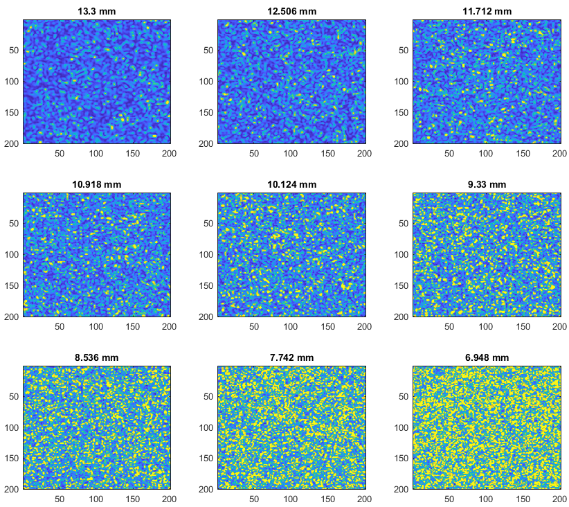
Right now I’m trying to simulate the relationship between speckle diameter and distance from the source (multimode fiber output): d = lambda*z/D, where d is the average speckle diameter, lambda is the light wavelength, D is the fiber core diameter, and z is the distance between the detector and the source (Goodman’s Speckle Optics). For reference, I am trying to simulate a long-coherence source outputted from a MMF which diffuses through a static medium before hitting a detector. I verified this experimentally a few months ago, where I incrementally decreased z, and was able to observe the speckle get smaller:
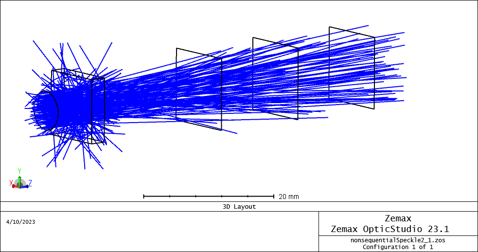
In Zemax I am using a non-sequential system with a long-coherence source ellipse and a detector, with a rectangular slab in between. The scattering model of the slab volume was set to Henyey-Greenstein with a mean path approximately 10% of the slab thickness. The 3D layout of the system looks fine, with most of the rays being scattered in various directions, and some hitting the detector:
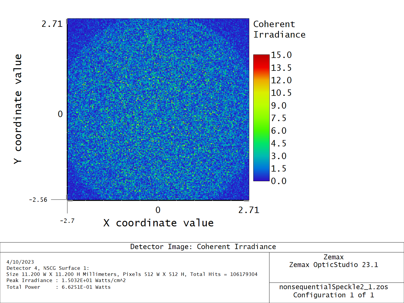
However, the pattern on the detector doesn’t quite look like the speckle you showed - it looks a lot more like pure noise, as opposed to having nice circular shapes in your figure:
The pattern doesn’t change much between the three detectors I placed, other than the irradiance decreasing with distance. Would you be able to share the file and/or parameters you used to produce the figure above? I would also welcome any other thoughts on this issue I’m having. Thank you so much in advance for any help you can provide!
@MelissaW: The model file I used previously is attached. I’m not sure how relevant it is for your case as it is just a simple demonstration of speckle generation via the coherence length parameter.
Regards,
Jeff
PS: I’m traveling this week, but will try to think more about your problem once I return.
Thank you so much @Jeff.Wilde for the detailed post and example! I’ll review and play around with the attached ZOS file soon. I really appreciate your help!