Solved

Zemax RAYTRACE


kivahan75


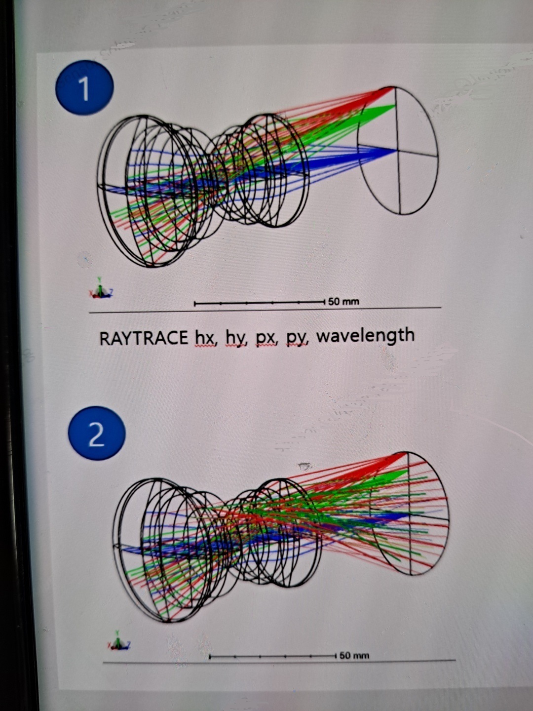
After the RAYTRACE command in Zemax, the coordinates of the ray, which arrived at the n-th surface of the RAGX(n), RAGY(n), and RAGZ(n) functions, are vertically straight as shown in Figure 1 below. Here, I would like to have ray arrive in the entire area of the n-th surface as shown in No. 2 in the picture below.
Is there a way?


Best answer by MichaelH

Hi Kivahan,

The RAYTRACE keyword will trace a single ray defined by [Hx, Hy, Px, Py].  The Hx/Hy terms define the normalized field coordinate while the Px/Py terms define the normalized pupil (Stop) coordinates. 

To “fill” the entire n-th surface, you will need to loop through all Hx/Hy field coordinates and the Px/Py pupil coordinates.  For specific planes, such as the image plane you show above, you will only need to change the Hx/Hy field coordinates.  If you just want a ring of rays at the n-th surface, then you can keep the Px/Py=0 (tracing just the chief ray for all the field points). 

The reason why the rays are “vertically straight” is because Hx is always 0 and Hy is only defined at 3 different values of [0.0, 0.707, 1.0].

Below is some pseudo-code that might be useful:

! use settings
px = 0
py = 0
wave = PWAV()
n = NSUR()

! loop through all the rays
FOR i = -10, 10, 1
  hx = i / 10
  FOR j = -10, 10, 1
    hy = j / 10

    RAYTRACE hx, hy, px, py, wave

    PRINT RAGX(n), ", ", RAGY(n), ", ", RAGZ(n)
  NEXT
NEXT
 

View original
Did this topic help you find an answer to your question?

2 replies

MichaelH
Ansys Staff
Forum|alt.badge.img+2
  • Ansys Staff
  • 352 replies
  • Answer
  • August 9, 2022

Hi Kivahan,

The RAYTRACE keyword will trace a single ray defined by [Hx, Hy, Px, Py].  The Hx/Hy terms define the normalized field coordinate while the Px/Py terms define the normalized pupil (Stop) coordinates. 

To “fill” the entire n-th surface, you will need to loop through all Hx/Hy field coordinates and the Px/Py pupil coordinates.  For specific planes, such as the image plane you show above, you will only need to change the Hx/Hy field coordinates.  If you just want a ring of rays at the n-th surface, then you can keep the Px/Py=0 (tracing just the chief ray for all the field points). 

The reason why the rays are “vertically straight” is because Hx is always 0 and Hy is only defined at 3 different values of [0.0, 0.707, 1.0].

Below is some pseudo-code that might be useful:

! use settings
px = 0
py = 0
wave = PWAV()
n = NSUR()

! loop through all the rays
FOR i = -10, 10, 1
  hx = i / 10
  FOR j = -10, 10, 1
    hy = j / 10

    RAYTRACE hx, hy, px, py, wave

    PRINT RAGX(n), ", ", RAGY(n), ", ", RAGZ(n)
  NEXT
NEXT


kivahan75
  • Author
  • Infrared
  • 12 replies
  • August 10, 2022

@MichaelH 

Great! Thank you for your help!!


Reply


Cookie policy

We use cookies to enhance and personalize your experience. If you accept you agree to our full cookie policy. Learn more about our cookies.

 
Cookie settings