Hi Kivahan,
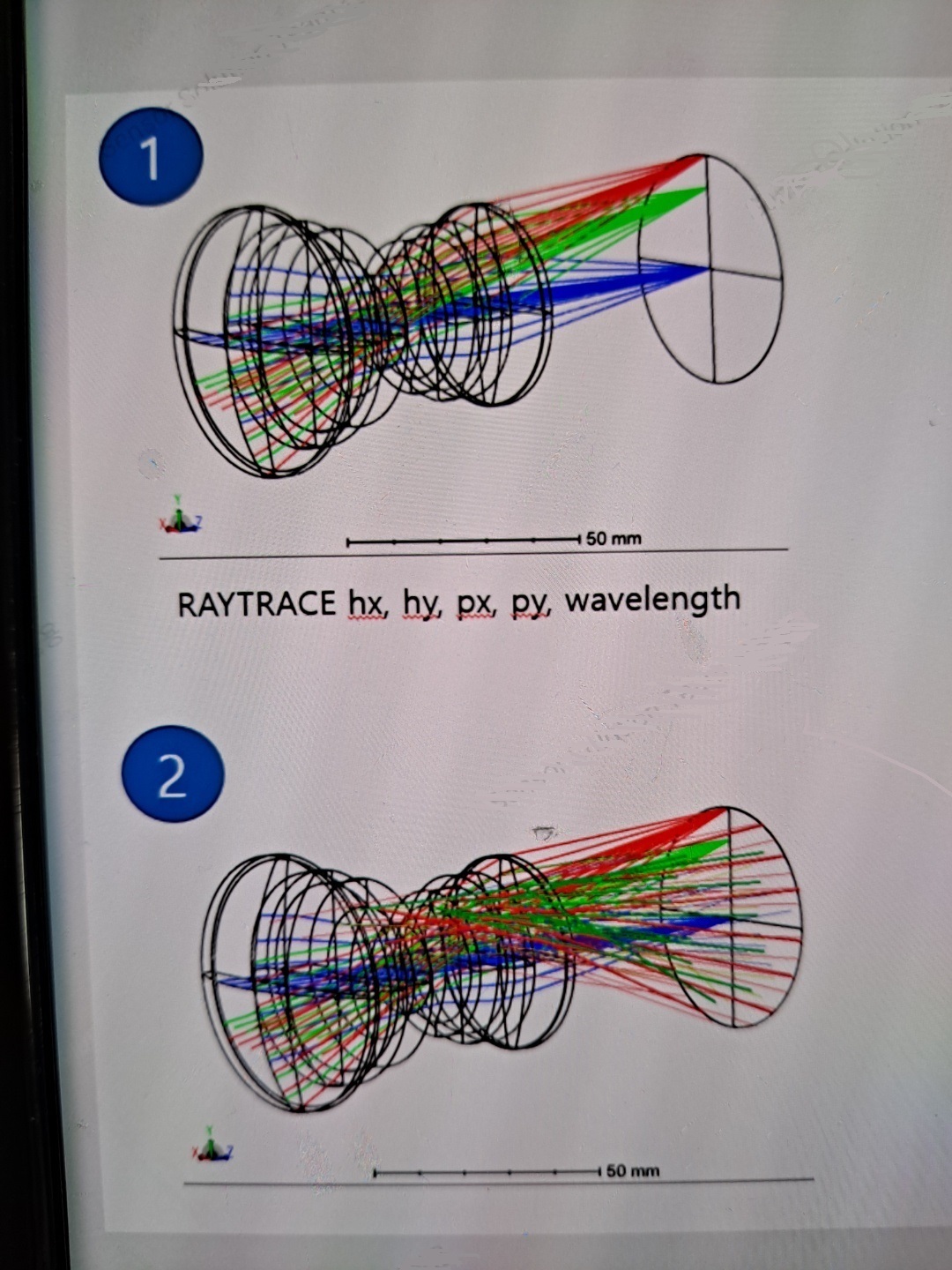
The RAYTRACE keyword will trace a single ray defined by [Hx, Hy, Px, Py]. The Hx/Hy terms define the normalized field coordinate while the Px/Py terms define the normalized pupil (Stop) coordinates.
To “fill” the entire n-th surface, you will need to loop through all Hx/Hy field coordinates and the Px/Py pupil coordinates. For specific planes, such as the image plane you show above, you will only need to change the Hx/Hy field coordinates. If you just want a ring of rays at the n-th surface, then you can keep the Px/Py=0 (tracing just the chief ray for all the field points).
The reason why the rays are “vertically straight” is because Hx is always 0 and Hy is only defined at 3 different values of [0.0, 0.707, 1.0].
Below is some pseudo-code that might be useful:
! use settings
px = 0
py = 0
wave = PWAV()
n = NSUR()

! loop through all the rays
FOR i = -10, 10, 1
  hx = i / 10
  FOR j = -10, 10, 1
    hy = j / 10

    RAYTRACE hx, hy, px, py, wave

    PRINT RAGX(n), ", ", RAGY(n), ", ", RAGZ(n)
  NEXT
NEXT