Hi, I’m getting started writing a video on Wide Angle Lenses for my YouTube Channel DesignOpticsFast. I have a couple of questions:
For Zemax Support:
I’m having trouble getting the ‘enhanced wide angle ray aiming’ to make any difference:
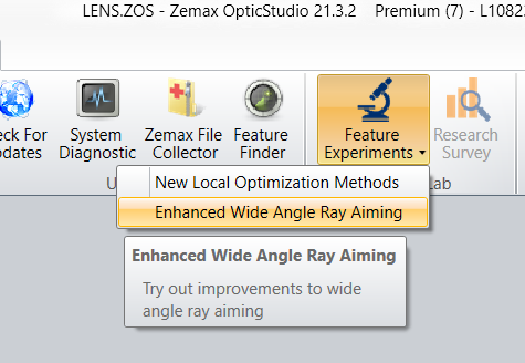
What does it do? I’ve toggled all the (new) switches under Ray Aiming in System Explorer and I’ve not been able to see any changes at all, let alone improvements. Can you guys explain where and when this Feature Experiment is intended to be useful? Or offer some sample files that show what it can do?
Also, I wanted to check that the Performance Test measures raytracing speed AFTER the ray-aiming, so it won’t be a useful guide to how well or badly the ray-aiming is going. Is that correct?
For Zemax Community:
I’m interested in problems that you have in designing wide angle lenses. I’m trying to write a How-To that gives a step-by-step guide to setting up a wide angle lens. One problem I have is that it works with 100% of the files I create, so I wonder if I’m missing something. If anyone could post the ZARs of a problematic wide-angle lens I’d love to take a look at it, and also just describe any problems specific to wide-angle lenses so that I can give a comprehensive coverage.
In short though, if you don’t have a system that causes problems for the old ray aiming algorithm then you are unlikely to see significant change with the new modifications. They were created specifically to address cases where the old system failed.
You should be able to compare the relative speed of different settings with the ‘System Updates per second’ values, but not ‘rays/ray surface per second’.
Chris
Thanks Chris!
Hi Chris,
I had some of the same questions as Mark. The link you provided is helpful, but what would be even better are 2-3 examples of different lens systems that exhibit the problems being addressed. Could you provide those?
Thx,
Jeff
I agree, it would be really helpful to see some examples of the new features actually delivering some improvement. That’s true of the optimization ‘improvements’ too.
Also, if anyone has a problem wide-angle lens but doesn’t want to post it here on the forum, please email the .ZAR file to me at markgnicholson (at) gmail.com.
Hello Mark, Jeff,
I tested and I think maybe the built-in example “Wide angle lens 200 degree field.zos” can be used to demo what problems this tool solved. Note the following test are done with latest beta which will be available soon in next release 22.1.
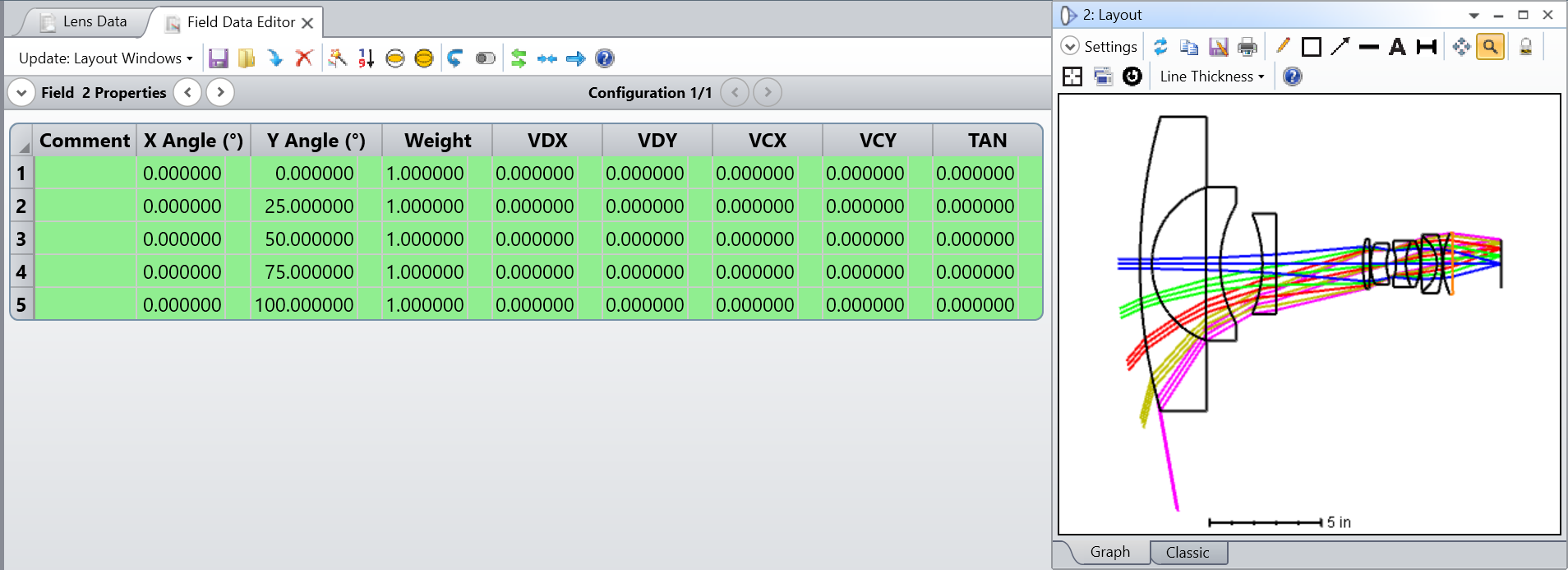
Open “Wide angle lens 200 degree field.zos” and it looks as below.
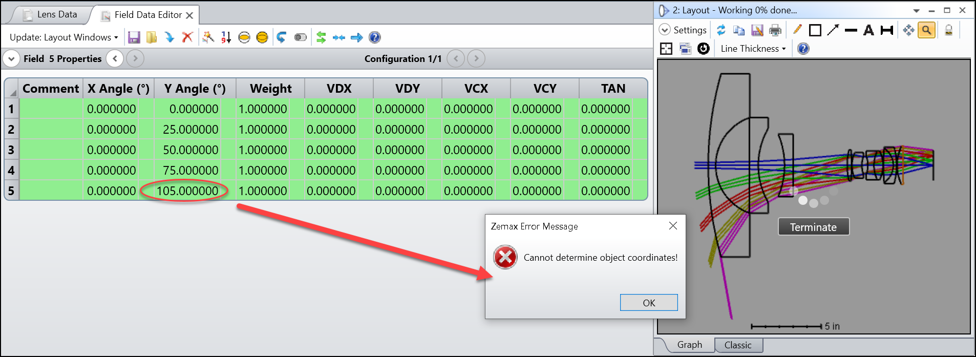
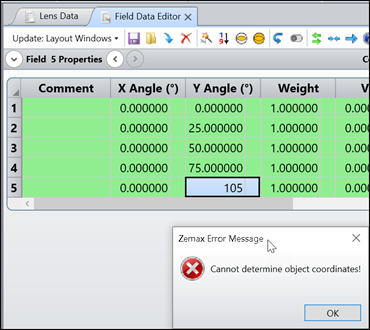
If I increase latest field by 5 degrees. It shows error “Cannot determine object coordinate!”. Usually this means physically there is not possible a ray can launch from 105 degrees in object space and finally reach the center of the STOP. (so it’s chief ray!) However, chief ray actually exist and it is the problem of the old Ray Aiming that cannot find it.
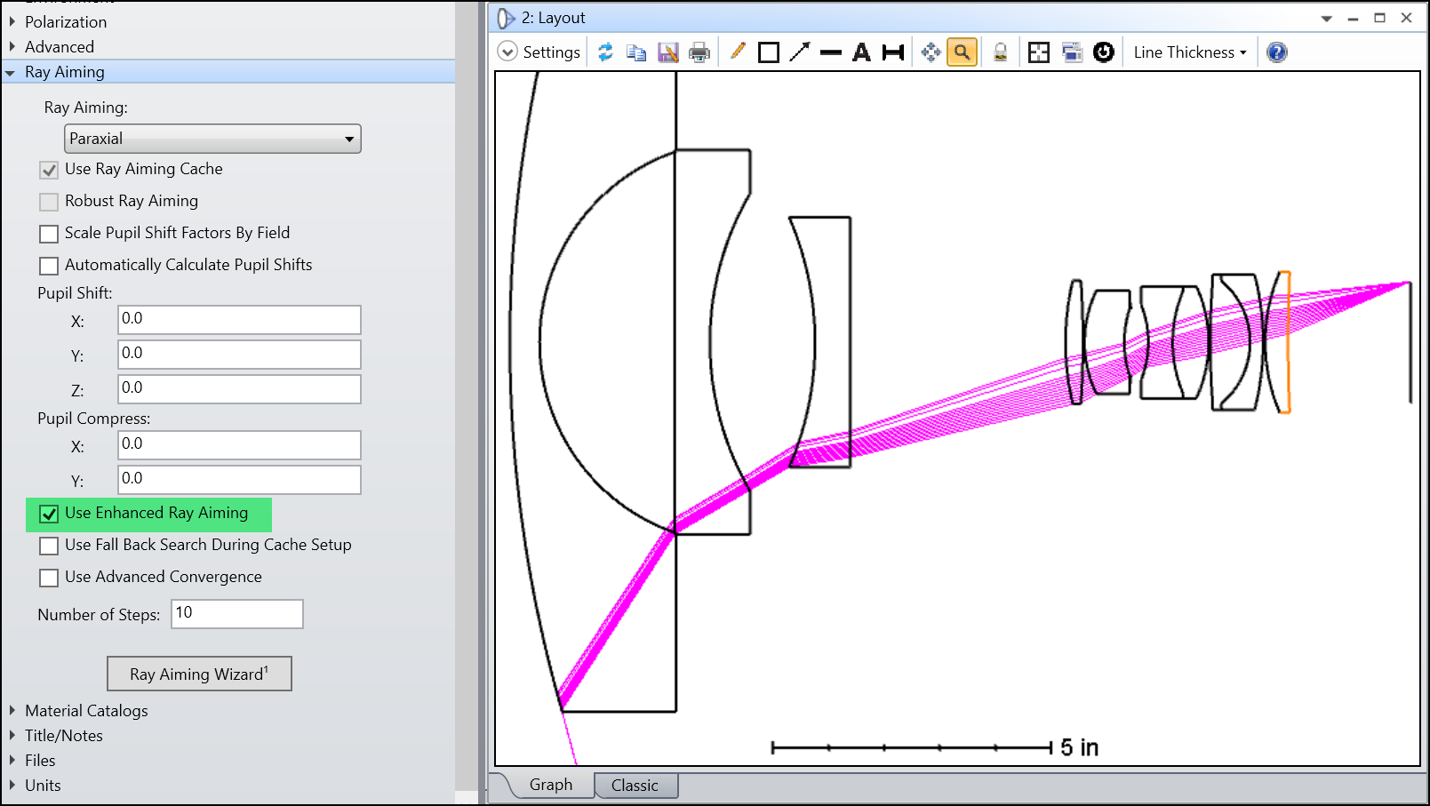
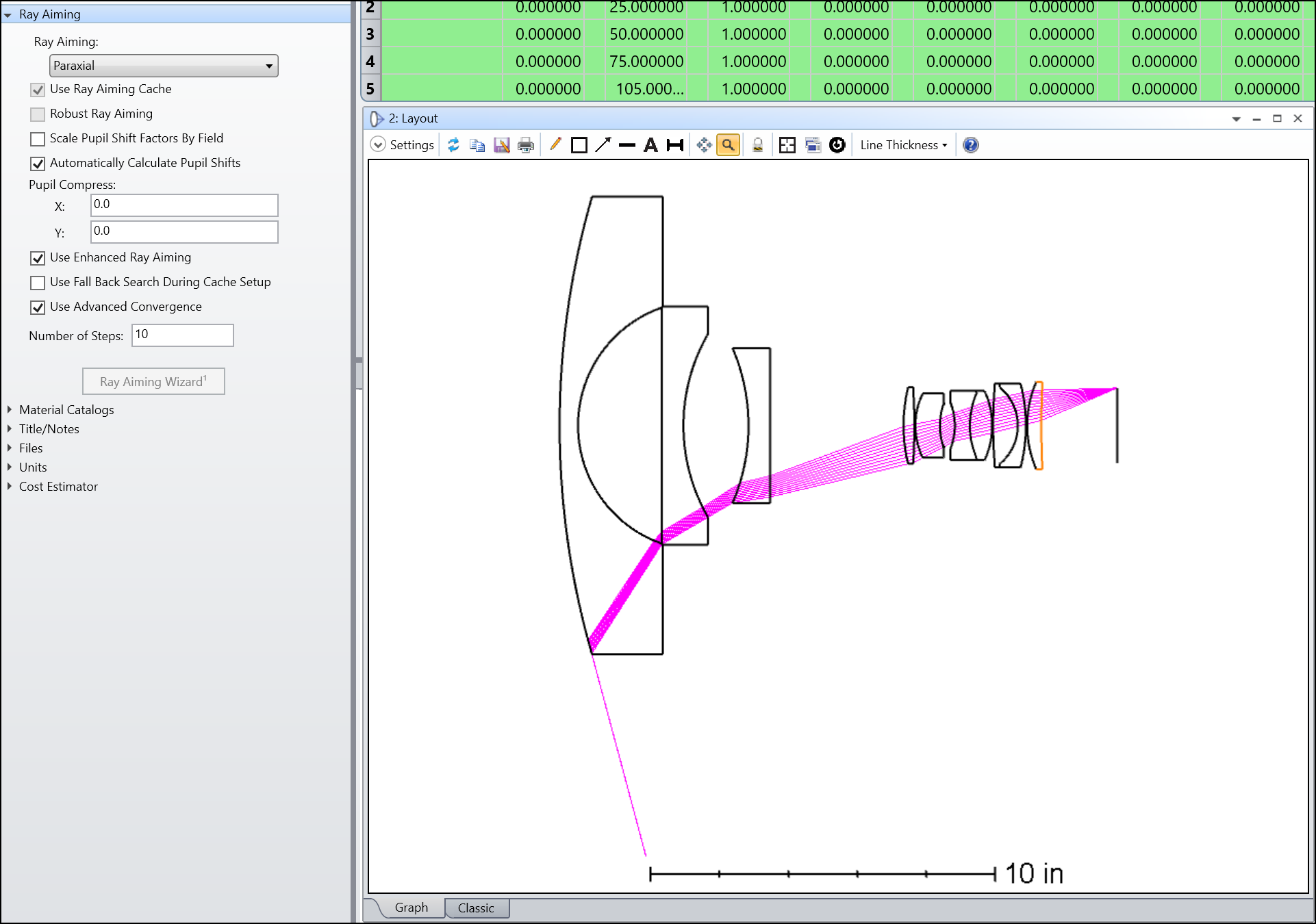
By unchecking the “Robust Ray Aiming” and checking the “Enhanced Ray Aiming”, it looks like we solved the problem.
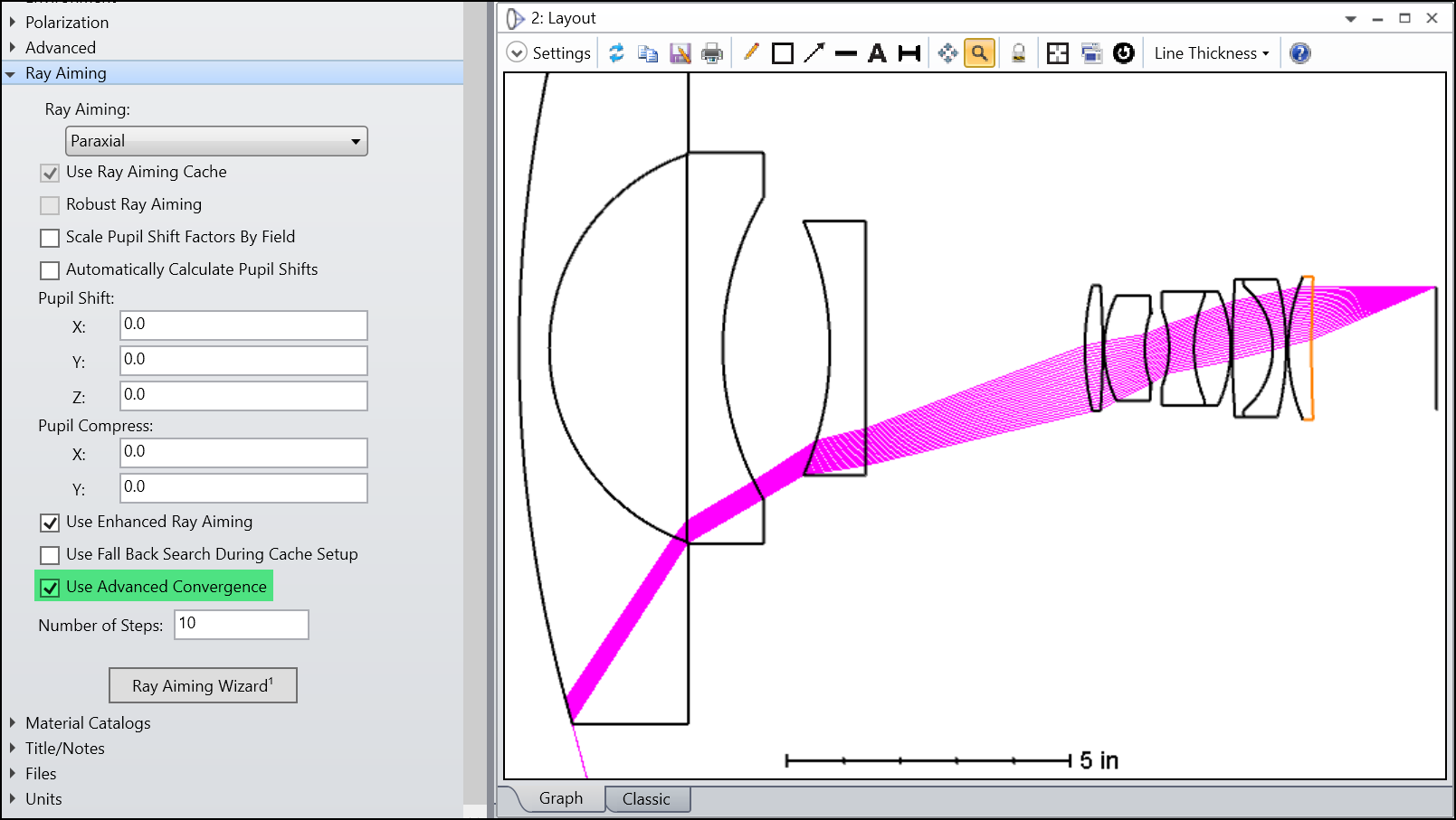
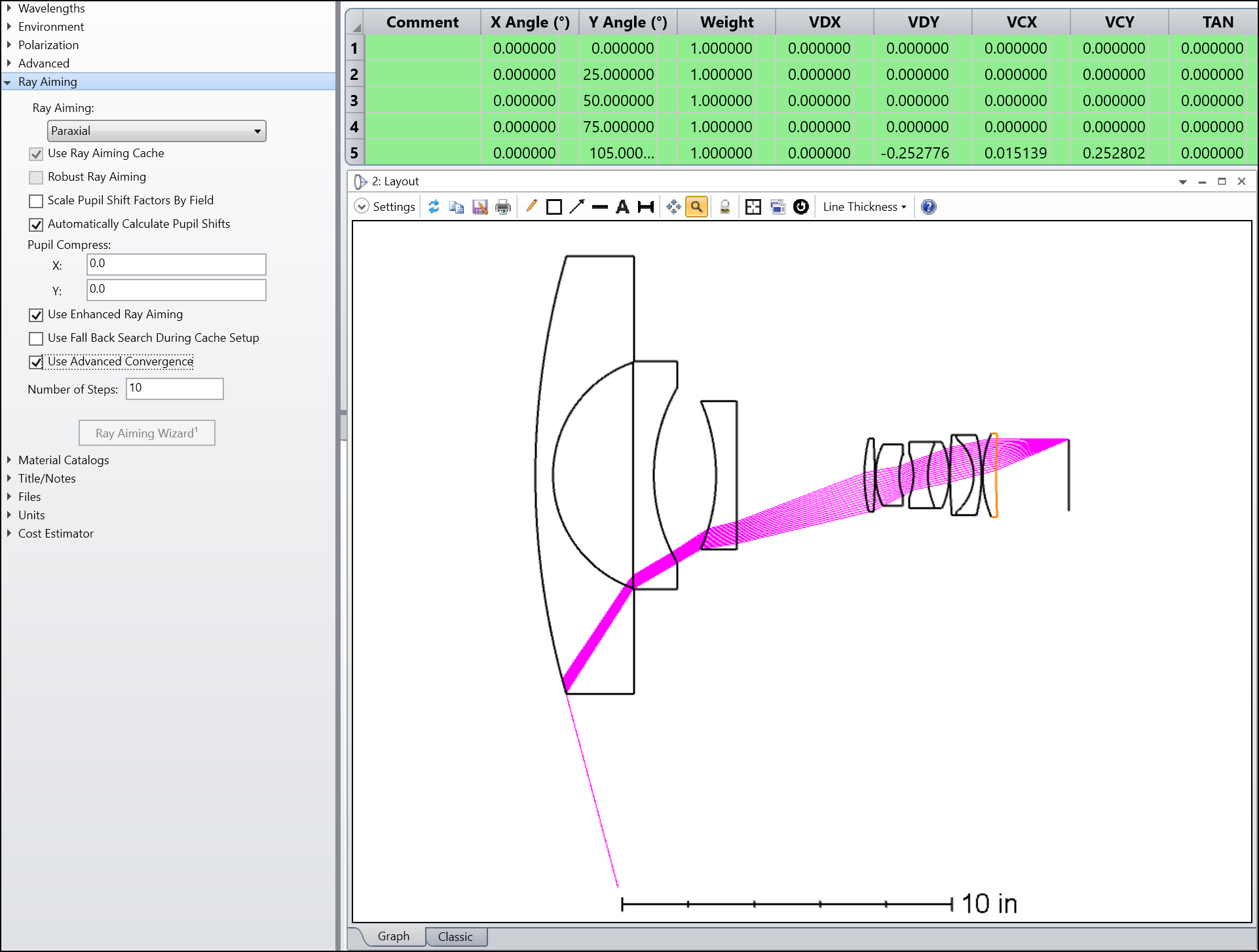
However, by further checking “Use Advanced Convergence”, we realized it was not solved because of many rays are missing.
I hope this is a good reference. Please let me know if you have any more questions.
Thank you!
Best regards,
Michael
Thanks Michael, I’ll try that
Hi Mark, I don’t have any specific file to share, but could you cover, if possible, how to keep high relative illumination when designing wide angle lenses?
Even with closed aperture (f8), I could not get a relative illumination higher than 65/70% when designing a wide angle lenses (eg 35mm for full frame sensor)
Hi Nicolo,
Well, a wide-angle lens already has much higher RELI than a fixed-pupil system, so it’s really doing very well in that regard already. If the lens followed cos^4 RELI would be zero by 90 degrees!
Think of a wide-angle lens as a lower-angle lens, with say 40 degree field of view and a fisheye extension. The fisheye maps the wide angle to the more moderate 40 degrees for the prime imager. That mapping is inherently anamorphic, and so we increase RELI at the cost of distortion. It’s a fundamental physical effect due to the shift, rotation and change of size of the entrance pupil as a function of field.
Mark
Hey @Michael Cheng ,
I’m working my way through your steps, and I found something I don’t understand/like. If I open the 200 degree file as you say, and set the largest angle to 105 degrees, nothing happens. The Field editor updates and draws the new field point on its x-y graph. But I get no ‘Cannot Determine Object Coordinates’ error.
Instead, the field editor updates, but the other windows do not. If I force them to update, I get ‘Unknown Error’. So, I see three problems here
The Field Editor updates normally and does not give an error.
The other windows do not update at all.
The error is ‘unknown’, and I think it should be a known error
So, something is breaking in the update code. I’m using 21.3.2, so your later beta may have the fix, but can you check this please? Failing silently and giving unknown errors is a backwards step.
Mark
P.S. Having said that, Enhanced Ray Aiming really does work well! Will this replace the existing Robust option, or still be an alternative to it?
Hmm...some more thoughts.
First of all, the enhanced ray aimer really does work. I was able to trace a ray that made an angle of 89.959 degrees to the surface normal! That’s really as close to grazing incidence as it’s possible to get. In contrast, the existing robust ray-tracer stops tracing at 104 degrees FOV (versus 105), and with an incidence angle maximum of 89.35 degrees. So, the new tracer really can get almost to grazing, and that’s a great achievement. Well done to Brian and the other developers.
I’m not sure yet about advanced convergence. In the example you give, where there are no vignetting factors used, advanced convergence does seem to trace rays that otherwise wouldn’t trace. But if vignetting factors are used. the opposite seems to be true.
When this feature launches, I think you guys should give clear guidance about the interaction of Vignetting Factors and the Ray Aiming options ’Scale Pupil Shift Factors by Field’, ‘Automatically Calculate Pupil Shifts’ and ‘Pupil Compression’. It would be really good to see old workarounds deleted from the dialog now you have this improved ray-aimer, or at the least clear guidance given on what should be used when.
Mark
Hi Mark,
Thank you for great feedback. These are very useful!!
1. For the behavior of “Unknown Error”, it’s actually a bug in 21.3. We have accidentally turned off the pop up of the error dialog. In the latest beta of 22.1, if I change the final field to 105 degrees, when leaving the cell, now I will immediately get the error dialog as below.
2. I agree. So far I didn’t see a case where Robust RA works but Enhanced RA doesn’t. It’s all opposite that Enhanced RA (ERA) can fix problems that Robust RA (RRA) cannot. Also, in the benchmarks, for those files that both works, ERA can usually be faster.
3. I didn’t test the vignetting factor, so this is an interesting point. Let me try to investigate it and get back to you! In my experience of testing, the Advanced Convergence mainly fixed a lot of problem caused by simply adding a CB with some non-zero value for Tilt Z. You can see what I meant by opening the Double Gauss example, turning on RA, and adding a CB with Tilt Z = 90. The error then shows as below.
I will come back if I know more with what happened with vignetting factors and thank you for tests and feedback again!:D
Best regards,
Michael
Thank you, Michael. You know, the bug may be the reason I didn’t see any changes with the Enhanced feature initially. When I made changes, everything was accepted and no error popped up, so I think I falsely identified the new code as not being any better than the old. In any case, once you allow for the lack of error message when the old code fails, the new code does seem better in every way.
Hi Mark,
You raise a good point that there are now a lot of options available for ray aiming, some may eventually be redundant, and navigating them all could be complicated. With this in mind we have updates coming with the new release including a new Feature Experiment that’ll setting up the right ray aiming settings for a system easier. It would be great to get feedback on these when they land.
Chris
Hi Chris,
It’s good to hear from you. If you want to shoot me a link to the beta, I’ll be happy to play with it.
I suspect that all the pupil-shift stuff is no longer required. That was added a long time ago when the robust ray-tracer needed more help than it does now. I’ll bet you lunch it doesn’t do anything useful anymore. It’s like the Matrix: you have to purge the old code
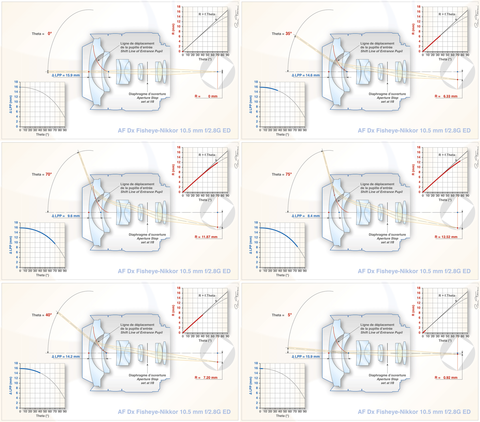
That said, I do think OS could have tools to visualize and report pupil shift. I’ve shown this graphic to everyone who’ll listen (and a few who won’t):
This is the most informative view of how a wide-angle lens works that I’ve ever seen, and I don’t think it can be reproduced in any current lens code. Michael Cheng wrote a macro that splits the lens into a configuration per field, and that’s the closest we have. But since pupil shift and rotation is how the wide-angle lens works and is really what makes a lens ‘wide angle’ compared to a fixed pupil system, I think we should have tools that show where the real entrance pupil is, as a function of field and wavelength, and some graphs of how it moves as per Pierre’s animation.
Mark
Hi Mark, just a quick update about the vignetting. I tested and can see some problems with the vignetting factor in 21.3, but the good news is they are all solved in the latest beta of 22.1. The following are pictures with and without vignetting factors in 22.1. I think they just works well now!
Sorry for the delayed reply. OpticStudio 22.1 is due to be released very soon. It would probably be easier just to wait for this, as it will contain the new feature experiments, rather than start testing a beta version now.
Chris
Since this thread is related to Wide Angle Lens, and as I was exploring Wide lens example in the sample library. I got stuck at this WAR coating that in manual says “Anti-reflection "W" coat, defined as a half wave of LA2O3 followed by a quarter wave of MGF2.” It would be glad if I could get some more insight into its understanding.
Hey @designerguy13-photonics,
The WAR coating is a wide-bandwidth AR coating. The standard AR coating is a quater-wave of Magnesium Fluoride, a quarter-wave thick at the design wavelength. The WAR coating puts a half-wave of La2O3 and this increases the useable range of the coating, and makes it more suitable for whole-visible-spectrum design sthan the simple AR alone. It has nothing to do with wide-angle, however