Solved

Understanding conversion from Jx Jy to Ex Ey Ez

  • 7 April 2021
  • 5 replies
  • 261 views

I have a very simple model that I want to completely understand, but seem to be having an issue with the sign of the electric field of the source ray.


Suppose I launch a single ray, with a YTilt of 10 deg and polarization of Jx=Jy=1 using the Z-axis as my polarization reference.  Then my initial K vector will be [x0.139173, y0, z0.990268].   According to the knowledgebase article (https://my.zemax.com/en-US/Knowledge-Base/kb-article/?ka=KA-01336#TypesPolarizationDependentMedia) , my S and P vectors are given by


S = k x Z = [x0, y(-0.139173), z0]

P = k x S = [x0.137818, y0, z(-0.019379)]


Now I would like to know precisely how S and P are converted to my initial electric field, E, which is not explicitly described by the aforementioned article.  My thought is to normalize each polarization vector by their magnitude,


Sn = S / |S| = [x0, y(-1), z0]

Pn = P / |P| = [x0.990268, y0, z(-0.139173)],


then to scale these normalized quanities by the relative Jx/Jy values and intensity as follows:


Sn' = Sn*sqrt(Jx / (Jx + Jy) * IntensityPerRay)  = [x0, y(-0.707106), z0]

Pn' = Pn*sqrt(Jy / (Jx + Jy) * IntensityPerRay)  = [x0.700225, y0, z(-0.098410)],


with IntensityPerRay=1 if I only have a single analysis ray in my system and my source power=1.  Finally we add these to get to the total electric field,


E = Sn' + Pn' = [x0.700225, y(-0.707106), z(-0.098410)],


from which we can recover the total intensity as Intensity = |E|^2 = 1.  While this makes sense to me, the result in Zemax Optic Studio has a sign flip in the y-component of the initial electric field.  It is 


E_zos = [x0.700225, y0.707106, z(-0.098410)]


Can anyone please explain why the sign is flipped in ZOS, or if there is an error in my approach?!  I have redone this simple math many times and cannot find any mistake.  The ZOS file of a very simple model is attached.  It is worth noting that if I change my Z definition to Z=[x0, y0, z(-1)], I do NOT recover the ZOS result.

icon

Best answer by Sandrine Auriol 7 April 2021, 10:47

View original

5 replies

Userlevel 6
Badge +2

Hi Joseph


My colleague Michael Cheng has created a macro that calculates the polarization. It can be found on the Code Exchange (please login to the be able to it):

It works in sequential mode (at least I was able to reproduce the results in sequential mode).


I have attached the file. I think you will be able to find the difference with the macro.


Let us know if not and we can have a look.


Hi Sandrine and Michael,


Thank you for your prompt response and the detailed macro that tracks the Jones matrix through sequential surfaces.  This is quite useful, however I do have a follow-up question.  I translated this code to a MATLAB script wherein I use my own 3D Snell's implementation and Fresnel coefficient calculation.  In order to get agreement with the Zemax result, I noticed several pecularities which I am hoping you might be able to clarify:


1. In the ZOS field editor, the X-Angle and Y-Angle values do not appear to directly correspond to a source with Y-tilt and X-tilt angles, respectively.  For example, if I define the X- and Y-Angles as 10deg and -40deg, respectively, the first transition matrix is


========== Surface 0 (STANDARD) ============

Material: AIR


Rotation matrix (transition):

0.752057766 0.000000000 0.659097198

0.000000000 1.000000000 0.000000000

-0.659097198 0.000000000 0.752057766


Using the convention described in to extract tilt angles from the rotation matrix, we obtain XTilt=ZTilt=0 and YTilt=41.23=sqrt(XAngle^2 + YAngle^2).   


However, if I were to compute ROTab(:,:,1) = Rz(ZTilt)Ry(YTilt)Rx(XTilt) with the field angles converted to tilts (XTilt=-40deg, YTilt=10), I would get for the first transition rotation matrix


ROTab(:,:,1) =


0.984807753012208 -0.111618897048950 0.133022221559489

0 0.766044443118978 0.642787609686539

-0.173648177666930 -0.633022221559489 0.754406506735489


This method leads to different results for all the vectors and ultimately very different Efield and intensity results.  In order to achieve the same results, I therefore redefine the tilt angles in the following way


YTilt = -40, XTilt=10

YTilt' = sqrt(XTilt^2 + YTilt^2),  XTilt'=0

ROTab(:,:,1) = Rz(ZTilt)Ry(YTilt')Rx(XTilt')


and I recover the first transition rotation matrix reported by the macro.  Is it therefore incorrect to equate the X- and Y-field angles with a source rotated by the same amount about the Y- and X-axes, respectively?  My concern in redefining the tilts is that some information may be lost regarding direction of the ray.  For example the incident ray k-vector for the first case is


0.659097197742238

0

0.752057766350650


whereas in the second case, it is 


0.133022221559489

0.642787609686539

0.754406506735489


I suppose what I am ultimately wondering is how does ZOS convert the specified field angles into tilt angles?

Note:  My actual application is a non-sequential diffractive system with NO rotational symmetry, which is why I am concerned about maintaining signs of the field (tilt) angles.

Userlevel 6
Badge +2

Hi Jospeh


The rotation matrix and tilts are described here: Rotation Matrix and Tilt About X/Y/Z in OpticStudio. I'm going to have a look at your description but you may go faster looking at the article.


Sandrine


Userlevel 6
Badge +2

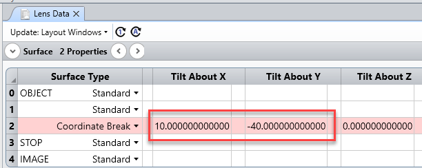
So for example I have defined a sequential system:


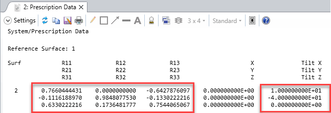
The GCRS (Global Coordinate Reference Surface) is set to 1. The Rotation Matrix in the Prescription Data is:


Then in non-sequential I have defined:


I can again read the rotation matrix in the prescription data:


So that is identical to the sequential mode.

Reply