Solved

Understanding conversion from Jx Jy to Ex Ey Ez

  • 7 April 2021
  • 5 replies
  • 261 views

I have a very simple model that I want to completely understand, but seem to be having an issue with the sign of the electric field of the source ray.


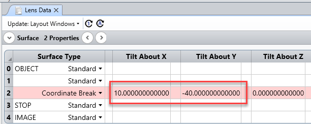
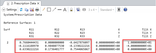
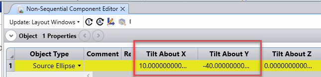
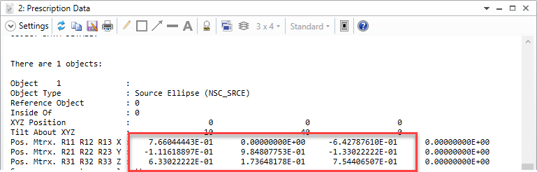
Suppose I launch a single ray, with a YTilt of 10 deg and polarization of Jx=Jy=1 using the Z-axis as my polarization reference.  Then my initial K vector will be [x0.139173, y0, z0.990268].   According to the knowledgebase article (https://my.zemax.com/en-US/Knowledge-Base/kb-article/?ka=KA-01336#TypesPolarizationDependentMedia) , my S and P vectors are given by


S = k x Z = [x0, y(-0.139173), z0]

P = k x S = [x0.137818, y0, z(-0.019379)]


Now I would like to know precisely how S and P are converted to my initial electric field, E, which is not explicitly described by the aforementioned article.  My thought is to normalize each polarization vector by their magnitude,


Sn = S / |S| = [x0, y(-1), z0]

Pn = P / |P| = [x0.990268, y0, z(-0.139173)],


then to scale these normalized quanities by the relative Jx/Jy values and intensity as follows:


Sn' = Sn*sqrt(Jx / (Jx + Jy) * IntensityPerRay)  = [x0, y(-0.707106), z0]

Pn' = Pn*sqrt(Jy / (Jx + Jy) * IntensityPerRay)  = [x0.700225, y0, z(-0.098410)],


with IntensityPerRay=1 if I only have a single analysis ray in my system and my source power=1.  Finally we add these to get to the total electric field,


E = Sn' + Pn' = [x0.700225, y(-0.707106), z(-0.098410)],


from which we can recover the total intensity as Intensity = |E|^2 = 1.  While this makes sense to me, the result in Zemax Optic Studio has a sign flip in the y-component of the initial electric field.  It is 


E_zos = [x0.700225, y0.707106, z(-0.098410)]


Can anyone please explain why the sign is flipped in ZOS, or if there is an error in my approach?!  I have redone this simple math many times and cannot find any mistake.  The ZOS file of a very simple model is attached.  It is worth noting that if I change my Z definition to Z=[x0, y0, z(-1)], I do NOT recover the ZOS result.

icon

Best answer by Sandrine Auriol 7 April 2021, 10:47

View original

5 replies

Userlevel 6
Badge +2

So for example I have defined a sequential system:


The GCRS (Global Coordinate Reference Surface) is set to 1. The Rotation Matrix in the Prescription Data is:


Then in non-sequential I have defined:


I can again read the rotation matrix in the prescription data:


So that is identical to the sequential mode.

Userlevel 6
Badge +2

Hi Jospeh


The rotation matrix and tilts are described here: Rotation Matrix and Tilt About X/Y/Z in OpticStudio. I'm going to have a look at your description but you may go faster looking at the article.


Sandrine


Note:  My actual application is a non-sequential diffractive system with NO rotational symmetry, which is why I am concerned about maintaining signs of the field (tilt) angles.

Hi Sandrine and Michael,


Thank you for your prompt response and the detailed macro that tracks the Jones matrix through sequential surfaces.  This is quite useful, however I do have a follow-up question.  I translated this code to a MATLAB script wherein I use my own 3D Snell's implementation and Fresnel coefficient calculation.  In order to get agreement with the Zemax result, I noticed several pecularities which I am hoping you might be able to clarify:


1. In the ZOS field editor, the X-Angle and Y-Angle values do not appear to directly correspond to a source with Y-tilt and X-tilt angles, respectively.  For example, if I define the X- and Y-Angles as 10deg and -40deg, respectively, the first transition matrix is


========== Surface 0 (STANDARD) ============

Material: AIR


Rotation matrix (transition):

0.752057766 0.000000000 0.659097198

0.000000000 1.000000000 0.000000000

-0.659097198 0.000000000 0.752057766


Using the convention described in to extract tilt angles from the rotation matrix, we obtain XTilt=ZTilt=0 and YTilt=41.23=sqrt(XAngle^2 + YAngle^2).   


However, if I were to compute ROTab(:,:,1) = Rz(ZTilt)Ry(YTilt)Rx(XTilt) with the field angles converted to tilts (XTilt=-40deg, YTilt=10), I would get for the first transition rotation matrix


ROTab(:,:,1) =


0.984807753012208 -0.111618897048950 0.133022221559489

0 0.766044443118978 0.642787609686539

-0.173648177666930 -0.633022221559489 0.754406506735489


This method leads to different results for all the vectors and ultimately very different Efield and intensity results.  In order to achieve the same results, I therefore redefine the tilt angles in the following way


YTilt = -40, XTilt=10

YTilt' = sqrt(XTilt^2 + YTilt^2),  XTilt'=0

ROTab(:,:,1) = Rz(ZTilt)Ry(YTilt')Rx(XTilt')


and I recover the first transition rotation matrix reported by the macro.  Is it therefore incorrect to equate the X- and Y-field angles with a source rotated by the same amount about the Y- and X-axes, respectively?  My concern in redefining the tilts is that some information may be lost regarding direction of the ray.  For example the incident ray k-vector for the first case is


0.659097197742238

0

0.752057766350650


whereas in the second case, it is 


0.133022221559489

0.642787609686539

0.754406506735489


I suppose what I am ultimately wondering is how does ZOS convert the specified field angles into tilt angles?

Userlevel 6
Badge +2

Hi Joseph


My colleague Michael Cheng has created a macro that calculates the polarization. It can be found on the Code Exchange (please login to the be able to it):

It works in sequential mode (at least I was able to reproduce the results in sequential mode).


I have attached the file. I think you will be able to find the difference with the macro.


Let us know if not and we can have a look.


Reply