Solved

Transfer circular lens data into a grid sag surface

  • 15 June 2022
  • 9 replies
  • 297 views

Hello everyone,

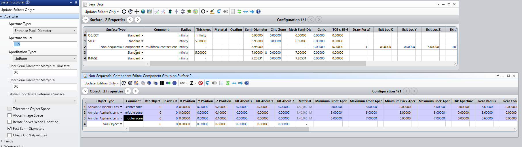
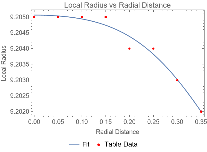
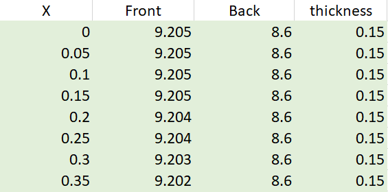
I want to simulate a contact lens in Zemax OpticStudio. What I am trying to do is to create a grid sag surface with all the real data surface I have from the contact lens. I have the distance from the centre of the lens (x), the anterior and posterior radius in each point of the lens, the thickness in each point and the index of refraction. An example is depicted in the following picture:


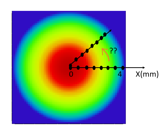
The data go until x=4mm, and this structure repeats rotationally all around the lens surface

I would like to know how I can input all this data into Zemax as a grid surface. For the moment, I know that I have to transfer the data into a matlab code (How to write a Grid Sag DAT file programmatically – Knowledgebase (zemax.com), but in this example, I can only use one value of radius, (in my case I put the posterior radius, 8.6mm). I would like to know how I can get a final file with the sag corresponding to each anterior radius (column 2 of my picture), that is varying with x, please.

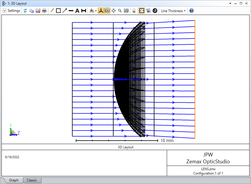
In the mentioned example, the data are transferred to a square grid, but I would like to do it as a circular grid/rotationally symmetric way, as the contact lens is circular. Is it possible? I tried to change the Surface > Aperture> Circular aperture of the surface but it does not work.

The idea of what I would like to do is depicted in the picture below (just an interpretation, it is not a real surface):

Do you think that the grid sag surface is the best for my what I need to do? If no, could you suggest me another surface type that I can use please?

Thank you very much, waiting for your answer

Alicia

icon

Best answer by David 20 June 2022, 02:56

View original

9 replies

Userlevel 7
Badge +2

Hi Alicia,


For those that are not familiar with contact lenses, can you explain how the front and back radii are defined?

Take care,


David

Yes! In this concrete example, the contact lens is a rotationally symmetric surface defined by an anterior radius that diminishes from the center to the periphery, and a posterior radius that is constant (the back surface is a sphere). Both surfaces are separated by a thickness that, in this case, is lower in the center than in the periphery of the lens. Every multifocal contact lens has at least three annular zones where different power values are defined. In my case, I have three different concentric annular zones, with a different conic constant for each of them. Generally speaking, the central zone has a power for distance vision, the next annular zone has a power for intermediate vision, and the last annular zone has a power for near vision.

I hope now is more clear, please ask me again if you have further questions

Userlevel 7
Badge +2

Hi Alicia,


It helps a lot thank you. I was hoping you could show us a diagram or a formula to determine the surface sag knowing those radii.

One suggestion I can give is that, among the freeform surfaces, the Cubic Spline, and Extended Cubic Spline are rotationally symmetric. Perhaps, you could use Python/MATLAB to fit your sag with a cubic spline, and then input those coefficients into OpticStudio? The cubic spline is still relatively smooth though. Perhaps you could just fit a polynomial to the whole surface (also with Python/MATLAB) and use the Extended Polynomial surface.

Hope this helps.

Take care,


David

Userlevel 7
Badge +3

Hi Alicia,

If you have three separate radial zones that each can be defined by the usual surface properties (radius, conic & thickness), can’t you simply construct the contact lens in a non-sequential layout using, for example, the Annular Aspheric Lens object (in this case using three separate objects, one for each zone), and then use it in either a fully non-sequential model or a mixed-mode model?  For example, here is simple mixed-mode example of the lens in air:


In this case I just left the conic equal to zero on the front surface in each zone because I don’t know what the appropriate values are.  If you need to model the contact lens as applied to the eye, then there is a non-sequential eye model available that could be included (OpticStudio models of the human eye). 

Regards,

Jeff


Userlevel 6
Badge +4

Hi Alicia,

I have also been thinking about this very interesting problem.

Suppose the lens you are modeling is radially symmetric and smooth enough to be modeled as an Even Asphere. Then we can use the general formula for the even asphere as a mathematical model for the curve.

For a two-dimensional curve written in the form y = f (x), the equation of curvature is:

The local curvature is the reciprocal of the local radius. So we can apply this formula to the equation describing the Even Asphere and arrive at an expression for the local radius as a function of radial distance in terms of the parameters of the Even Asphere.

This expression, out to original terms of order 6 in r and with the conic constant assumed zero, is this:

I derived this expression using Mathematica and fit it to your data, with the following result:


(Note: It is really the base radius of curvature. It is only the curvature at r = 0 for spherical surfaces.)

I have attached a zip folder containing a Mathematica notebook and a PDF print of the same. I tried to make it readable, but reading it might still be awkward for those not familiar with Mathematica. Of course, Matlab or Python could be used to perform the same task.


Userlevel 6
Badge +4

I might add that there is more than one solution to the fit. These parameters are obtained when requiring c > 0, but the resulting surface sag is the same:


Userlevel 6
Badge +4

And attached here is a zip containing a ZAR file of the lens.

Hello everyone,

Thank you very much for your replies! I have been working first with the mixed suggested by Mr Wilde and in the following days I will try to apply the Even asphere fitting from David.

I think the mixed mode model works! But I have two questions for Mr Wilde: you suggested to place a non sequential eye model behind the lens but,  is it also possible to place a sequential eye model after the lens with the same effect?

Also, you placed two standard surfaces before and after the Non sequential component to define the entry and ending ports, right? Is there any possibility to remove these surfaces, or they are always needed in mixed mode models?


Thanks a lot, best regards

Alicia

Userlevel 7
Badge +3

Hi Alicia,

For a mixed-mode model, the non-sequential (NSC) surface serves as the input port.  The surface following the NSC surface, which serves as the exit port, must be a flat standard surface with no curvature.  Also, the background refractive index for the NSC space is defined by the material setting of the NSC surface.  No objects inside the NSC group should touch or overlap with the entry or exit ports.  Therefore, if air is used for the background index inside the NSC group, there must be air gaps immediately after the entry port as well as immediately before the exit port.  More detail can be found here: How to model a mixed sequential/non-sequential system.

These restrictions would seem to make it impossible to place a mixed-mode contact lens object close to or touching a sequential eye model.  That’s why I suggested using an NSC eye model in which the contact lens could be easily placed in contact with the first surface of the eye.  Of course a similar model could be constructed using the fully non-sequential mode (which by definition does not require entry/exit ports).  For a fully sequential model, you may have good luck using the fitting method suggested by David.

Regards,

Jeff

Reply