Tilt system

  • 23 November 2020
  • 5 replies
  • 377 views

Userlevel 1

Hi all,


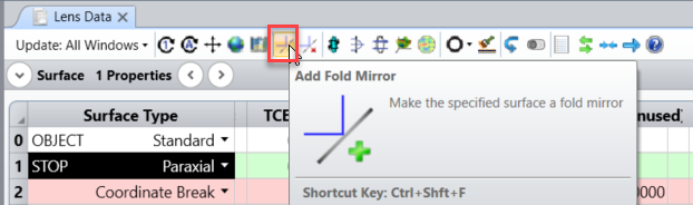
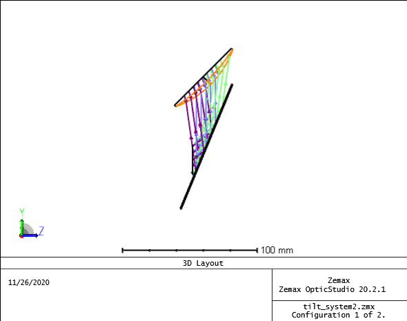
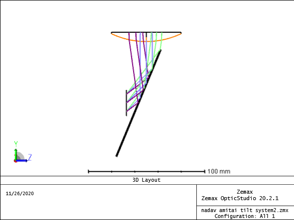
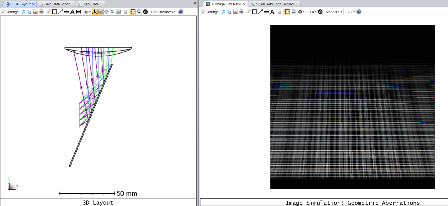
As a part of collimating system i used mirror to fold the rays.


I got a tilted image but I do not found the reason for that.


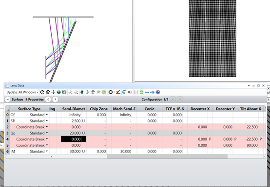
Maybe something in coordinate breaks?


Thanks,


Nadav


5 replies

Userlevel 5
Badge +2

Hello Nadav,


Thanks for your question here!


Yes, this is because of the settings of the Coordinate Break surfaces. If you would like to add a fold mirror to your system you need to use the same tilt angle on the second Coordinate Break as on the first one, i.e. you need to use a Pick up solve with +1 scale factor and not -1.


The easiest way to set up your fold mirror is to use the Add Fold Mirror tool in the Lens Data Editor:


You may find a detalied description about this tool in the Help file at:


The Setup Tab > Editors Group (Setup Tab) > Lens Data Editor > Lens Data Editor Toolbar > Add Fold Mirror


You may find a sample file that is provided with Zemax under {Zemax}\Samples\Sequential\Tilted systems & prisms\Tilted mirror.zmx.


For further references, please check out the following knowledge base articles and webinars:


Exploring Sequential Mode in OpticStudio


How to model a scanning mirror


There's a tool for that! - webinar


If you have further questions, please ask and we will be happy to help!


If you would like to send a file, the best way to do it is to share the archive file (.ZAR) :


This will contain all the necessary information. Unfortunately, the .ZDA session file is not enough to reproduce the system, at least the .ZMX lens file should be included. You may read more about the file extensions here:


Zemax file extensions


Best,


Csilla


Userlevel 1

Hi Csilla,


Thanks for the help.


 I tried the above advice, but there is still tilt.


Best regards,


Nadav


Userlevel 5
Badge +2

Hi Nadav,


Thanks for your follow-up post and for sharing your file here!


I think the tilt in the image was caused by the last Coordinate Break in your system. There should be one tilting Coordinate Break before the fold mirror and one after. However, you used an extra Coordinate Break with a tilt, maybe to locate the lens properly, and this is what resulted in a tilted image. If you change the last Coordinate Break to use a decenter instead of a tilt to locate the lens in the beam then you will not see tilt in the image. You will only see the effect of the lens in this case.


Also, please note, that after mirrors thicknesses always change sign. You may find more information about the sign convention in the Help file at:


The Setup Tab > Editors Group (Setup Tab) > Lens Data Editor > Data Columns > Thickness


Please find my modified file attached.


If you need anything more clarifying, please ask!


Best,


Csilla


Userlevel 1

Hi Csilla.


Thanks for the quick reply.


Maybe it something with my software, but the output or your file is look like:


Instead of:


Userlevel 5
Badge +2

Hi Nadav,


Thanks for getting back to me!


It wasn't your software or computer, that is how the system looked like in my previous file. I only focused on the tilt in the image and corrected it by eliminating the last 45 degree tilt from the system. I didn't realize that you wanted to have a system where the image plane is perpendicular to the stop surface.


So in this case, if you would like to keep the overall arrangement of the system, then I think you will need to change the field definition from angles to object height. The difficulty in using field angle for defining the object field of view is that field angle units are inherently anamorphic. X-direction angles represent a different subtended angle at a Y angle of 80 degrees than at an a Y angle of 10 degrees. If field angles are being used, and the field of view is fairly wide (more than about 40 degrees in any direction),  then great care should be taken in interpreting the results for an extended object. As both of the above criteria was true for your system, therefore it distorted the image simulation results a lot. So it is better to change to object height field definition.


You may read more about this in the Hlep file at:


The Analyze Tab (sequential ui mode) > Image Quality Group > Extended Scene Analysis > Image Simulation


I converted the fields with the built-in tool, and now the results look better:


Please find my file attached.


If you have further questions, please let us know and we will be happy to help!


Best,


Csilla


Reply