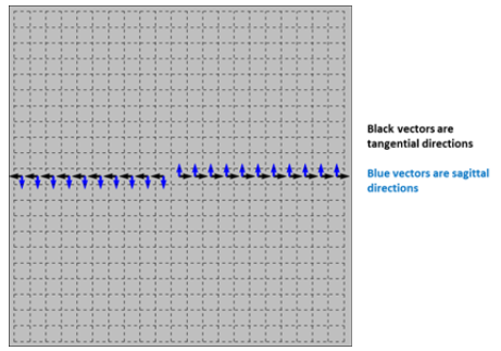
I have a rotationally symmetric system.I don't know why the tangential focus is different from the sagittal focus.Thank you very much for answering my question.

This answer is going to have to be verified by someone with source code access. 


IN a system that is rotationally symmetric and on-axis, there is no sagittal or tangential direction. OpticStudio just uses X and Y axes, but it doesn't matter: all data is exactly the same whatever choice you make of sagittal and tangential direction.


In the Power Map features, we trace a ring of rays around a central reference ray, and then compute for each ring ray its crossover or point of closest approach to the reference ray. That gives each ray's focal length, reciprocal is power. So we then have a set of data for each point.  The spherical power is given by the average power over the ring of rays. The maximum and minimum powers are the extreme values over the ring of rays. 


This is the bit that needs to be verified by a developer: On-axis, there is no way to choose sagittal and tangential directions, and I belive that OS is choosing the the direction of Max power to be S and of min power to be T (or vice versa). Certainly the data being returned is the same as the maximum and minimum powers.


I'm not sure what the 'right' answer is in this case and it may be that OS should write a warning when S and T powers/focal lengths are being reported, that says that the max and min powers/focal lengths are being used. Certainly S and T are only meaningful when you have a non-zero field point, as you can take the field points chief ray location, and draw a line through that and the center of the image and define S and T relative to that line.


But whatever, I think this just shows that you cannot define S and T uniquely when on axis.


- Mark


Hi Eason and Mark


I think it has to do with our definition of sagittal and tangential. There is a good article that was written by one of our developers: Understanding the geometry in OpticStudio Curvature Cross-Section analysis.


If you plot the X or Y power of the surface, you will find this difference too.


Let me know if that helps. 


Sandrine


Hi Sandrine,


Shawn's article is really good, but I still think that in this case the Power Map is using Max/Min for S and T. Is that correct?


- Mark


Hi Mark


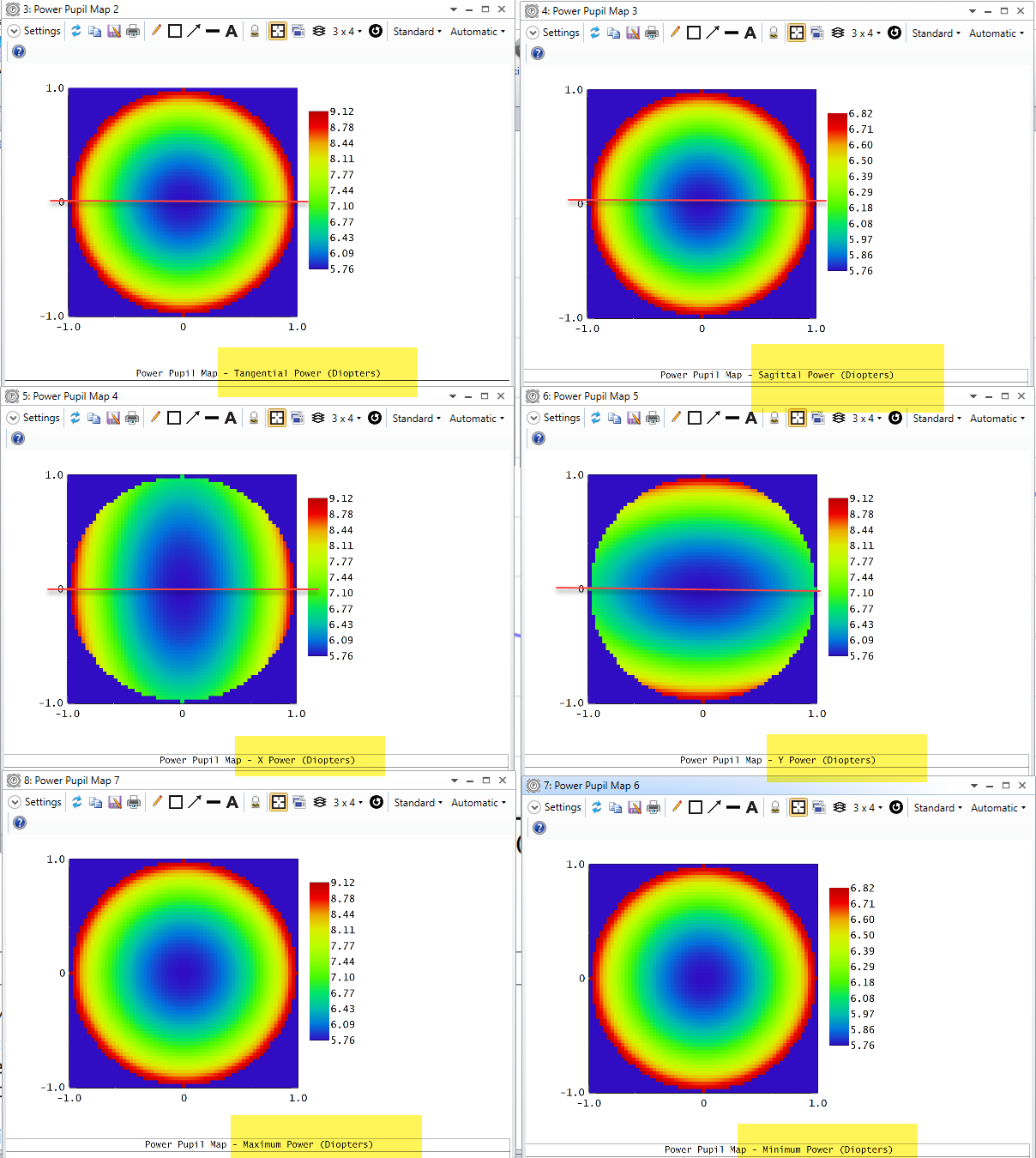
I have plotted the max, min, sagittal, tangential, X and Y power. Here is what I have:


So yes the tangential and the maximum power are identical and the sagittal and minimum power are identical. But I think this is expected for a rotationally symmetric system. The tangential direction is going towards the edge, whereas the sagittal direction is in the 'inside/circular' direction. 


I then did a check by vignetting the pupil (VCX=VCY=0.9). I then decentered the pupil by VDX=0.9 and optimized the back focal distance for the RMS spot radius.


- With a weight Y=0, I found 89mm, so that is a power of 11D. That would be the 'tangential' power.


- With a weight X=0, I found 151mm, so that is a power of 7D. That would be the 'sagittal' power.


So to me that makes sense. But I'll ask someone else to check because I don't like to disagree with you. I may be missing something. 


Sandrine


Reply