
Best answer by David
Hi Pumpkin,
I am not sure on what you are trying to do, but a few comments might help.
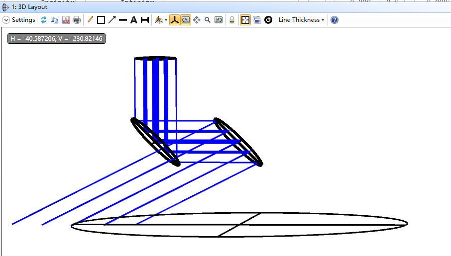
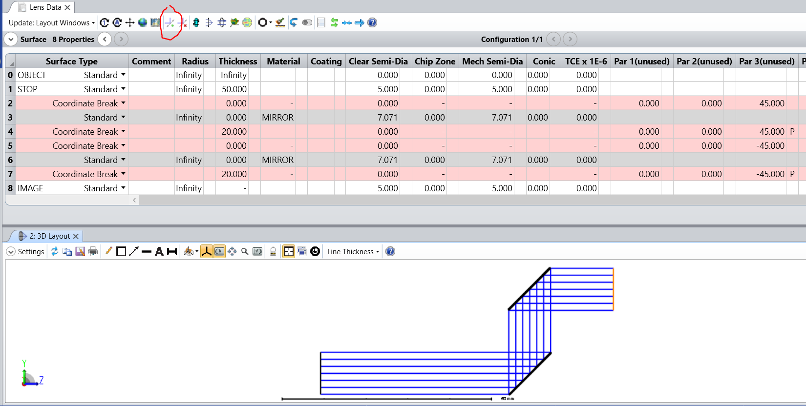
In the layout above it appears likely that the reflection law is obeyed, but the point of view in the 3D layout makes it appear otherwise.
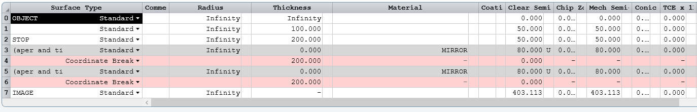
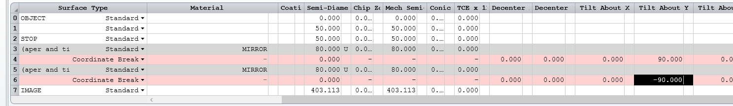
The layout appears to not match the LDE in that the signs of distances in the LDE are not negated after the mirror. Negating distances after a mirror in necessary in order to model the reversed ray travel.
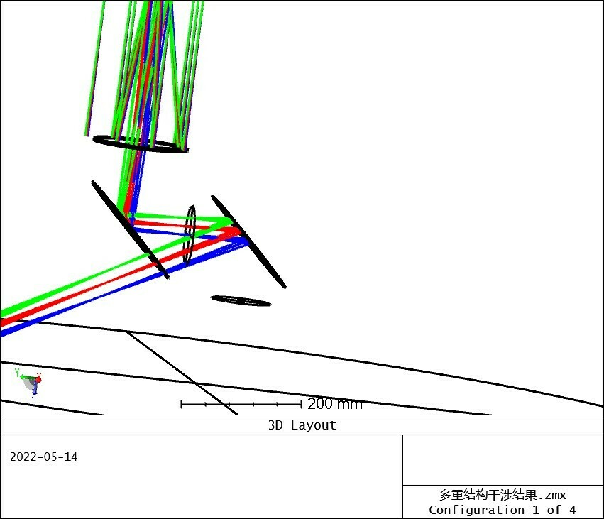
The best way to set up systems like this is by using the Add Fold Mirror tool in the LDE menu bar. I suggest reviewing the article How to Model a Scanning Mirror. Also, look up the Add Fold Mirror tool in the help system.
I attach an example. If you have further questions I suggest you attach your design as a ZAR archive file within a ZIP file. You can create the ZAR file using Save As. The ZAR file will let others see your design just as you see it.
Enter your E-mail address. We'll send you an e-mail with instructions to reset your password.
Do not provide any information or data that is restricted by applicable law, including by the People’s Republic of China’s Cybersecurity and Data Security Laws ( e.g., Important Data, National Core Data, etc.).
不要提供任何受适用法律,包括中华人民共和国的网络安全和数据安全法限制的信息或数据(如重要数据、国家核心数据等)。