I am working with a CPC (Compound Parabolic Concentrator) and have some questions about what’s happening with it. I understand that a maximum length is allowed, but shorter lengths seem to have a performance reduction as rays outside the acceptance angle are passing through, so maybe the maximum length is the correct length, but shorter CPCs are allowed if the user needs them.
More crucially, I am seeing that some rays above the critical angle are passing through while some rays below the critical angle are reflecting back out. What’s going on? Is there a bug?
Best answer by Kevin Scales
These are good questions, and the answer may not be clear at first. To start with your first question, you are correct. To get the full effect, you should set the Length parameter on your CPC to be equal or higher than the maximum allowed value by the equation given on the help page. This is the length for which the concentrator power is designed. You can select smaller lengths if you wish, for whichever reasons you may wish one, but the maximum length is the one to use for correct reflection.
The second question is a little trickier, but we can look at it with some test cases that I will go over here. A zipped copy of the system is attached to this post.
First the answer, and then the explanation. For meridional rays entering the CPC, the acceptance angle is absolute. Except in the specific case of a ray that hits a vertex at the end of the CPC (which is always a problem), these rays will pass through completely if below the acceptance angle and reflect back if above. At exactly the acceptance angle it is indeterminate, but even a slight tilt above or below this will completely filter the results as desired.
For skew rays the situation is different. More details and derivations are found in the source of CPC information as listed in the help page: "High Collection Nonimaging Optics" by W. T. Welford and R Winston, Academic Press (1989). But to summarize here, skew rays can sometimes pass for angles that are too high and reflect out for angles that are too low. This is a known behavior and is not a bug or a design flaw. It is simply a consequence of the geometry of the CPC.
For an explanation, a parabola has the known property that all on-axis rays focus to a single point. The CPC makes use of this by rotating the parabola about the CPC axis such that meridional rays entering at the extreme angle will hit the rim of the exit aperture. The rotation axis of the CPC is not the axis of the parabola. (A CPC in profile will not look parabolic. The wide aperture will have its walls parallel to the CPC axis.) With the most extreme angle hitting the rim of the aperture (the edge-ray principle), lower angle rays will exit somewhere inside the aperture, while higher rays will eventually reflect out. This covers all of the meridional rays that are possible but says nothing about skew rays.
It turns out that most skew rays follow this principle too. This forum posting is not the place to go into a detailed analysis of how to evaluate the skew ray effect formally, but we can use the tools of OpticStudio to create a graph of the effect for some representative input rays.
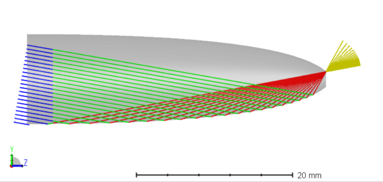
For strictly meridional rays, I used a Source Point array of 21 points and a CPC with an acceptance angle of 10 degrees. For an actual angle of 9.9 degrees as the Tilt About X parameter, we can see that all rays entering the CPC will exit the far end.
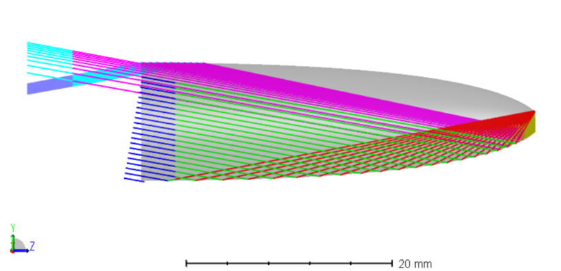
For 10.1 degrees, all rays reflect out. (Note that I have two detectors here, invisible for edge-on viewing, causing the ray color change on the left side.)
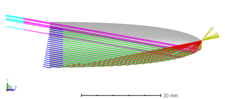
At exactly 10 degrees, the situation is indeterminate, as seen below. Specific examples will vary in how many rays are passed or rejected.
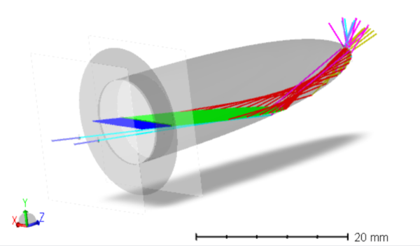
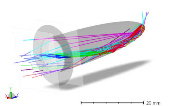
These are all expected results, as the meridional case is well-modeled by designing to the edge-ray principle. For skew rays, we can now look at the same situation, but with a 21 point source array oriented along X rather than Y. With an input angle of 9 degrees, we can see that most rays pass through, but a couple do reflect back out.
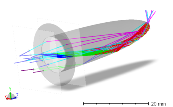
At an input of 10.1 degrees, most reflect out but a few pass through.
Unsurprisingly, at exactly 10 degrees, there is a mixture of roughly equal numbers through and rejected.
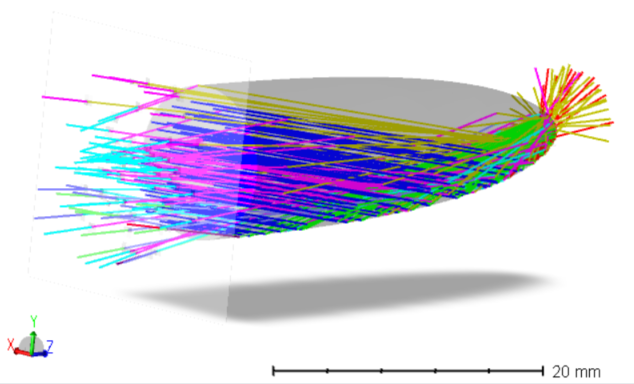
To get a better idea of how a wider beam would behave, we can use a Source Ellipse tilted at exactly the acceptance angle.
This is not very illustrative, as the number of rays quickly gets uncountable. Here we can use the Universal Plot 1D to work through a better numerical notion of what is happening. For the meridional, skew, and full disk cases, we can plot the power on the back side detector against the tilt angle. For the meridional case, the graph is unsurprisingly simple.
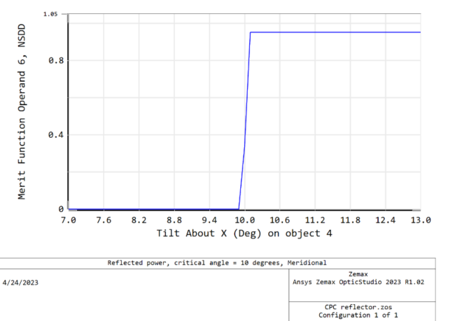
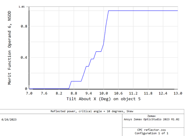
For the skew case, we see that the result is asymmetric and much broader. My reasoning for the choice of angles earlier is clear now. In this example, angles above critical are quickly extinguished but angles below it continue to reject rays for a couple degrees or more. Other specific examples may show different details in the shape of the curve, but each user can easily set this sort of analysis up on a case-by-case basis.
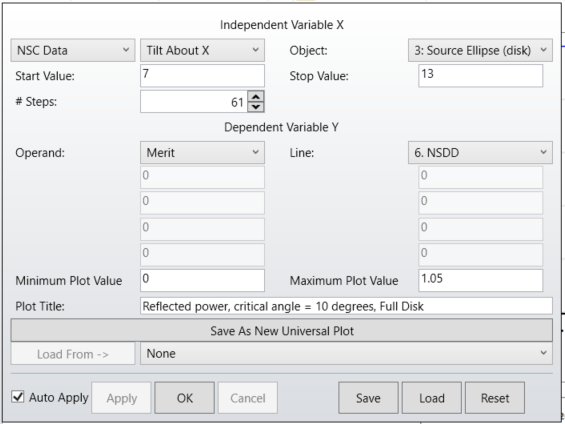
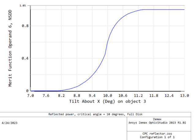
For the full disk case, we can get a smoother curve. I used this selection of settings for the universal plot after using the Optimization Wizard to create a basic Merit Function to read the power off one detector. The attached same files have a second detector on the small end for users who wish to look at passed rays rather than reflected.
This gives us a good final representation for the angular dependence on the CPC rejection of rays. It is close to symmetric but not entirely. With this information in mind, you can determine how a given CPC will behave in your system.
These are good questions, and the answer may not be clear at first. To start with your first question, you are correct. To get the full effect, you should set the Length parameter on your CPC to be equal or higher than the maximum allowed value by the equation given on the help page. This is the length for which the concentrator power is designed. You can select smaller lengths if you wish, for whichever reasons you may wish one, but the maximum length is the one to use for correct reflection.
The second question is a little trickier, but we can look at it with some test cases that I will go over here. A zipped copy of the system is attached to this post.
First the answer, and then the explanation. For meridional rays entering the CPC, the acceptance angle is absolute. Except in the specific case of a ray that hits a vertex at the end of the CPC (which is always a problem), these rays will pass through completely if below the acceptance angle and reflect back if above. At exactly the acceptance angle it is indeterminate, but even a slight tilt above or below this will completely filter the results as desired.
For skew rays the situation is different. More details and derivations are found in the source of CPC information as listed in the help page: "High Collection Nonimaging Optics" by W. T. Welford and R Winston, Academic Press (1989). But to summarize here, skew rays can sometimes pass for angles that are too high and reflect out for angles that are too low. This is a known behavior and is not a bug or a design flaw. It is simply a consequence of the geometry of the CPC.
For an explanation, a parabola has the known property that all on-axis rays focus to a single point. The CPC makes use of this by rotating the parabola about the CPC axis such that meridional rays entering at the extreme angle will hit the rim of the exit aperture. The rotation axis of the CPC is not the axis of the parabola. (A CPC in profile will not look parabolic. The wide aperture will have its walls parallel to the CPC axis.) With the most extreme angle hitting the rim of the aperture (the edge-ray principle), lower angle rays will exit somewhere inside the aperture, while higher rays will eventually reflect out. This covers all of the meridional rays that are possible but says nothing about skew rays.
It turns out that most skew rays follow this principle too. This forum posting is not the place to go into a detailed analysis of how to evaluate the skew ray effect formally, but we can use the tools of OpticStudio to create a graph of the effect for some representative input rays.
For strictly meridional rays, I used a Source Point array of 21 points and a CPC with an acceptance angle of 10 degrees. For an actual angle of 9.9 degrees as the Tilt About X parameter, we can see that all rays entering the CPC will exit the far end.
For 10.1 degrees, all rays reflect out. (Note that I have two detectors here, invisible for edge-on viewing, causing the ray color change on the left side.)
At exactly 10 degrees, the situation is indeterminate, as seen below. Specific examples will vary in how many rays are passed or rejected.
These are all expected results, as the meridional case is well-modeled by designing to the edge-ray principle. For skew rays, we can now look at the same situation, but with a 21 point source array oriented along X rather than Y. With an input angle of 9 degrees, we can see that most rays pass through, but a couple do reflect back out.
At an input of 10.1 degrees, most reflect out but a few pass through.
Unsurprisingly, at exactly 10 degrees, there is a mixture of roughly equal numbers through and rejected.
To get a better idea of how a wider beam would behave, we can use a Source Ellipse tilted at exactly the acceptance angle.
This is not very illustrative, as the number of rays quickly gets uncountable. Here we can use the Universal Plot 1D to work through a better numerical notion of what is happening. For the meridional, skew, and full disk cases, we can plot the power on the back side detector against the tilt angle. For the meridional case, the graph is unsurprisingly simple.
For the skew case, we see that the result is asymmetric and much broader. My reasoning for the choice of angles earlier is clear now. In this example, angles above critical are quickly extinguished but angles below it continue to reject rays for a couple degrees or more. Other specific examples may show different details in the shape of the curve, but each user can easily set this sort of analysis up on a case-by-case basis.
For the full disk case, we can get a smoother curve. I used this selection of settings for the universal plot after using the Optimization Wizard to create a basic Merit Function to read the power off one detector. The attached same files have a second detector on the small end for users who wish to look at passed rays rather than reflected.
This gives us a good final representation for the angular dependence on the CPC rejection of rays. It is close to symmetric but not entirely. With this information in mind, you can determine how a given CPC will behave in your system.