System F# Change Due to Parallel Plate in Collimated Beam

  • 10 February 2023
  • 3 replies
  • 134 views

Userlevel 3
Badge

Dear Community,

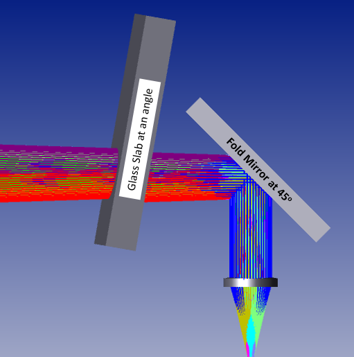
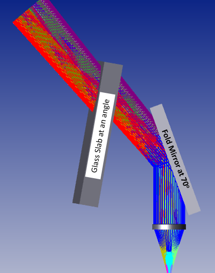
Does system F# change if we will place a parallel plate at an angle (Glass slab) into the collimated beam coming at different angles (System FOV)? 

I think It should not!!!! as both the surfaces of glass slab is flat (or having no power).

I am attaching couple of screenshots for the same.

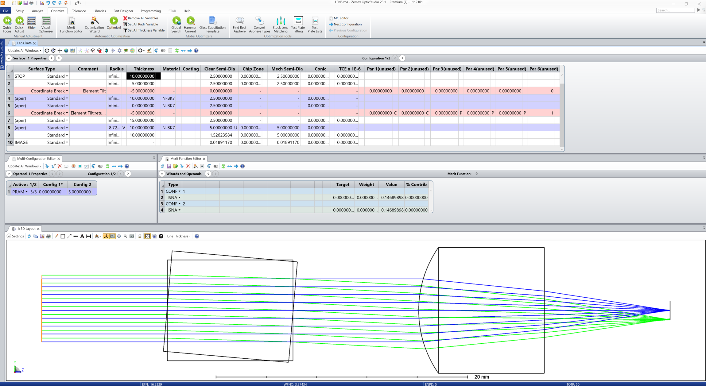
In the below screenshots I am keeping the Glass Slab position same for all Fold mirror rotation angle (45 to 70 Degree), with the help of couple of Coordinate Breaks (CB). 


Fig1: Fold Mirror is at 45 Degree Tilt angle.
Fig2: Fold Mirror is at 70 degree Tilt angle.


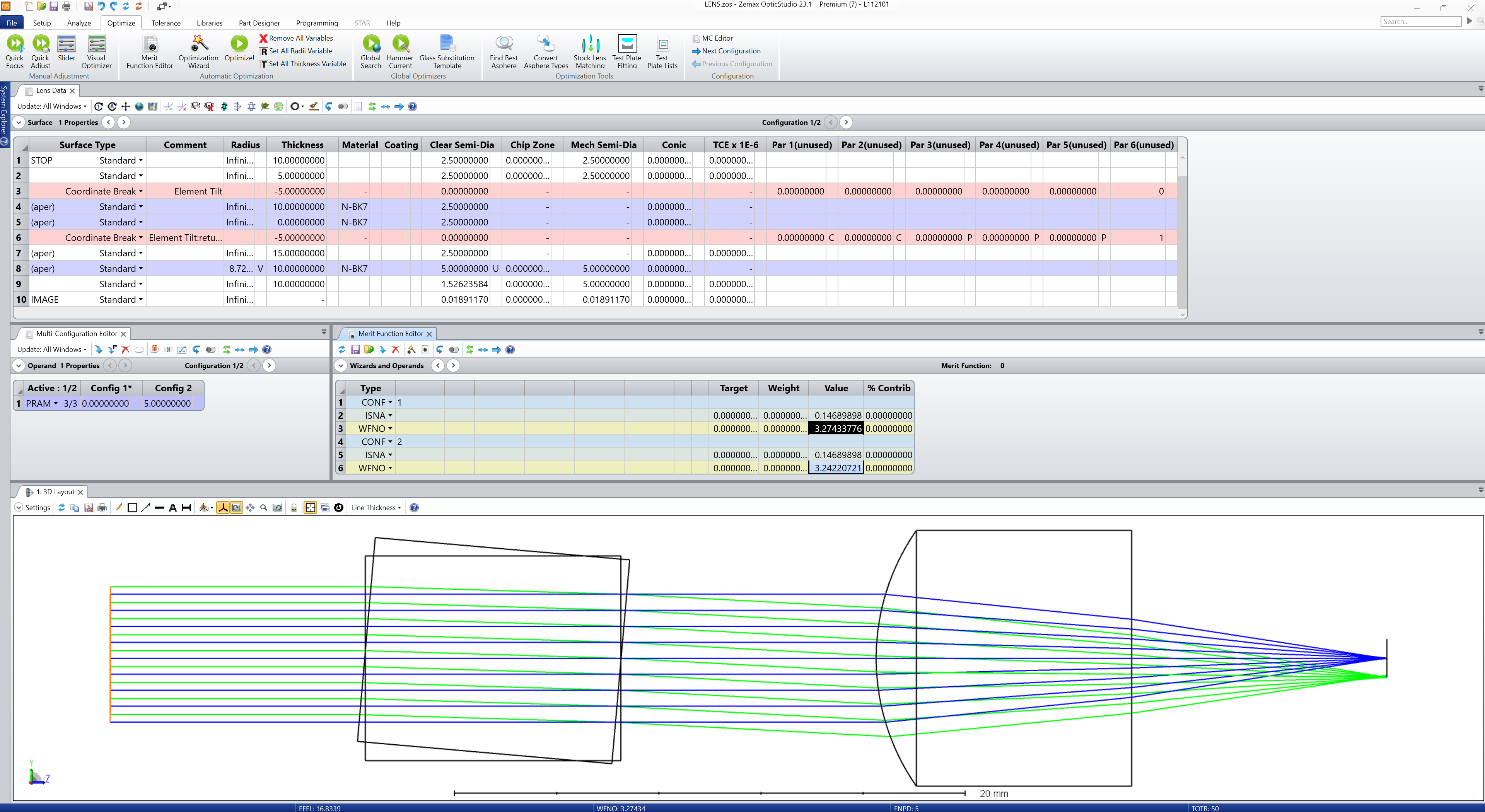
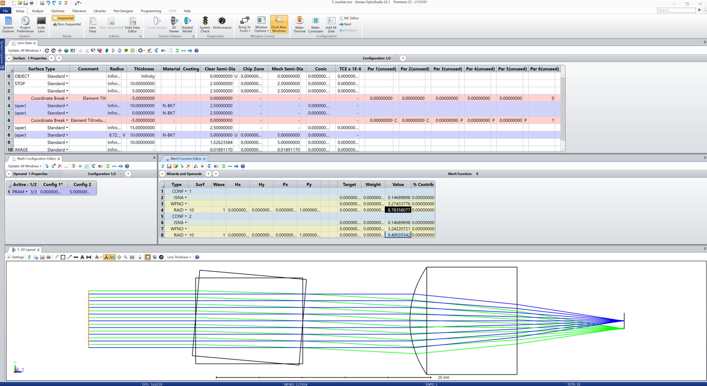
The system F# is different for above two configurations. Is this the real scenario?

Or, System F# should remain same irrespective of fold mirror tilt?


Thanks.


3 replies

Userlevel 7
Badge +2

Hi Chandan,


It depends how you measure the F/#. There are at least two definitions in OpticStudio. The Merit Function operand ISFN is the paraxial infinite conjugate F/# and is calculated as the paraxial effective focal length divided by the paraxial entrance pupil diameter. In this case, it is true that the parallel plate doesn’t affect the calculation of the F/# as demonstrated in the small example below:

As you can see, the beam is laterally shifted in the image plane due to the angled parallel plate, but the ISNA operands return the same value in each configuration (rotation of the parallel plate).

However, if you are talking about the Working F/# or WFNO. This is a different story because it is calculated as:

where W is the working F/# and theta is the real marginal ray angle. In this instance, there will be a difference is the lens is not paraxial. The parallel plate will shift the beam laterally and it will hit a portion of the lens that has different aberrations to it. As a result, the real marginal real angle changes and so does the working F/#:

Does that make sense? I’m attaching my file for your reference.

Take care,


David

Userlevel 3
Badge

Thanks for comment David, 

It is making sense. 

Same is experienced by me while doing this analysis in our design.

From the above comment it is clear that WFNO will change as we change the scan mirror tilt angle. But a MWIR sensor of particular F# is used in the design. If F# (WFNO) keep on varying for different fold mirror tilt (because ray will hit the glass slab at different angle) how we can use this detector???

(In your attached Zemax file I think you are changing the Glass slab tilt to see the effect on F#. But In my case I am keeping the glass slab tilt constant while rotating the scan mirror and hence the rays will hit the slab at different angle. Though, I am also getting the same effect WFNO changing, Paraxial F# remains constant.)

Do we need to consider Paraxial F# for the analysis, while ignoring the WFNO?


Thanks.


Userlevel 7
Badge +2

Hi Chandan,


I did simplify your case by omitting the mirror and tilting the slab instead. But the problem remains the same, the parallel plate will displac the beam, and if, as a result, the rays fall on the lens at a different location, whether it is due to a mirror or something else, the working F/# will be different. Think about it this way: if the marginal ray angle changes, then the working F/# will change as well. You can use a RAID (or any other angle) operand to display the marginal ray angle theta:

As you can see, RAID shows different values already. Therefore, WFNO has to be different.

I’m not sure what you are trying to achieve at the moment, so I can’t advice further. Do you have a sensor that you are trying to model in OpticStudio? If this is the case, and the sensor has a fixed F/#, I would just adjust the STOP size to match the F/#. The rays that fall outside the stop due to the mirror tilt will be vignetted and reduce the relative illumination.

I hope this help. Take care,


David

Reply