For a pancake type of VR, most of the straylight issue comes from the imperfect polarizer model. Here we have provided an example that users can play with for investigation.

The components in the system are as below.
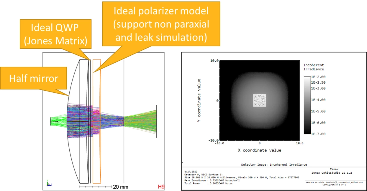
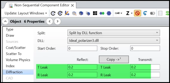
In the polarizer (object #6), users can control the light leakage at reflection and transmission side. The polarizer is based on this paper but with some modifications: Non-paraxial idealized polarizer model
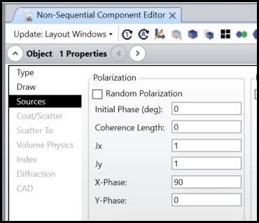
Note the input light is with circular polarization.
 

Enjoy!

Hi Michael,

this is great, thank you!

I have a question on the dll. I read the paper you referenced and that the dll is based on. It seems to me that the authors’ main claim for their model is that it is independent of refractive index. Is that correct? Assuming that you do have the traditional no, ne, and crystal axis vector, does the model have any benefits over polarization ray-tracing with the birefringent mode on?

I must confess I have not run your model yet 😱so I’m just curious about when I’d use the dll in real life.


-Mark


Hi Mark!

Thank you for feedback!

Yes, this is an ideal polarizer that is independant of the exact material (and its refractive index) and structure that made the polarizer.

This DLL is not related to a birefringent material. It’s only for polarizer. The paper first derives the equation for birefringent material, but then simplify it to a isotropic (nomal) materials. And then further simplify the equation for ideal polarizer. The advatage of this model compared to just Jones Matrix is it works more realistically for non-normal incident rays. I have further added some parameters to approximate the behavior that the blocked direction of polarization  can still leak even for nomal incidence.

The derivation in this paper is possible to be used for building a “surface model” that represents a thin film of a homogenous birefringent material. However, it will be quite same as you simply build the model by an volume object with given birefringent material.

One thing I’m  thinking is maybe we can extend the equation from uniaxial to biaxial materials, then it will support some speical components such like Faraday Rotator, but this will take time.:)


Thanks! I’m still not quite sure  I understand the benefits of this over birefringent ray tracing. I get the benefit that index data isn’t needed. But if you have the index data, how well does this model compare to the real thing?


I would like to first mention again this DLL doesn’t use any of the birefringent raytracing. The paper start from birefringent material but ignore it at its final ideal polarizer model.


But it’s possible to compare the birefringence model built in this paper (although it’s not used later) to our model in OpticStudio.

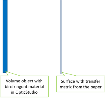
As shown below left side, in OpticStudio we can build a volume for a thin plate with given no, ne, and cristal axis for raytracing. We can use “waveplate mode” to ensure o-ray and e-ray are combined when leaving the volume object.

On the other hand, the model in this paper works similar to this scence. It can be applied as a surface with zero thickenss as shown at right side. If the volume at left side is thin enough, the two models will behave same. I think this answers “If you have the index data, how well does this model compare to the real thing?”. If we have real index data, what this model do is to simplify a thin volume to a thin surface. That’s what I would say.:)


That’s really helpful, thank you 🙏


Thank you for discussion, Mark. It’s nice to talk to you!


Hi Michael,

Thank you so much for sharing model! I have a question about the QWP in your model. I found you used A_real = 1 and D_img = -1 for QWP simulation, however accordoring to manual, is it supposed to be A_real = 1 and D_img = 1 for QWP?

Best,

Kaden


Hi Michael,

Thank you so much for sharing model! I have a question about the QWP in your model. I found you used A_real = 1 and D_img = -1 for QWP simulation, however accordoring to manual, is it supposed to be A_real = 1 and D_img = 1 for QWP?

Best,

Kaden

Hi Kaden,

I’m glad you like it. If you check the wiki page: Jones calculus - Wikipedia, you will find it’s only about the coordinate as below.

It’s even possible to rotate the QWP to any coordinate and the Jones Matrix will be like below.


I hope this helps.

Thank you!


Best regards,

Michael


Hi Michael, 

First of all, thanks for sharing. 

I have some questions, I'm not quite sure if I understand the function of the ideal polarizer. Does it act like a PBS or is it a beneficial element for minimizing stray light? 

Kind regards, 

M.Romero 


Hi Miguel,

The ideal polarizer act like an ideal PBS but not based on a real data or for minimizing straylight. If you have some real coating data, you can consider to use static link for an accurate PBS or QWP simulation.

Thank you.


Michael


Reply