
Dear all
There's a problem on my INF3 fiber simulation - NSC mode
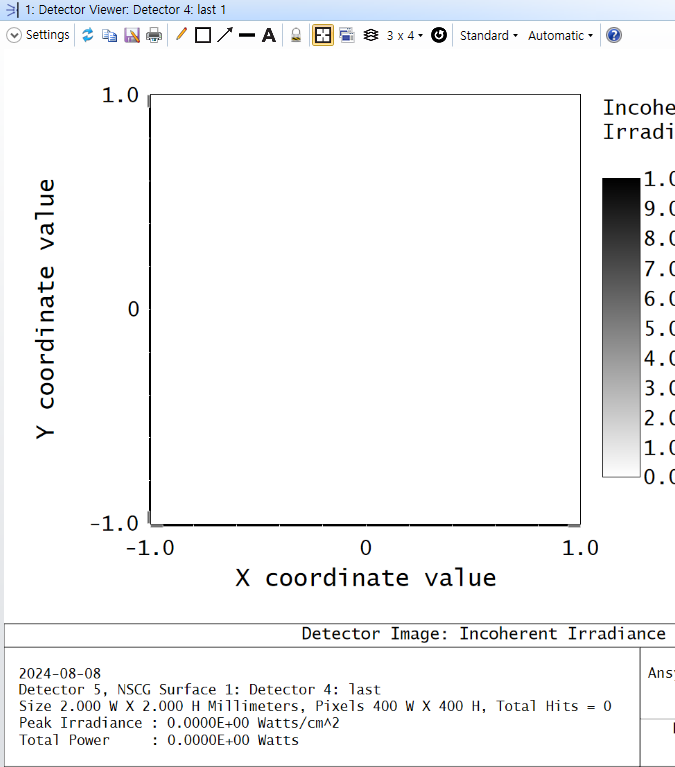
Simulation doesn't run well with the torus volume. There's a large amount of power loss up to 99.6% when the lights propagate from source to last detector (calculated by detector at the right end of fiber).
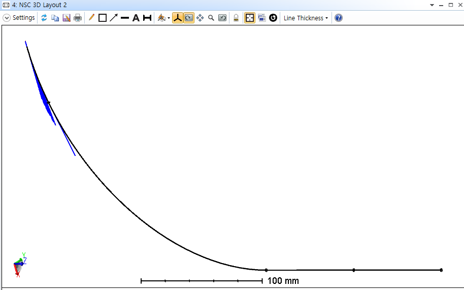
I just have verified that 'Total Power' varies as I change the value of 'Rotation R' from Torus Volume object.
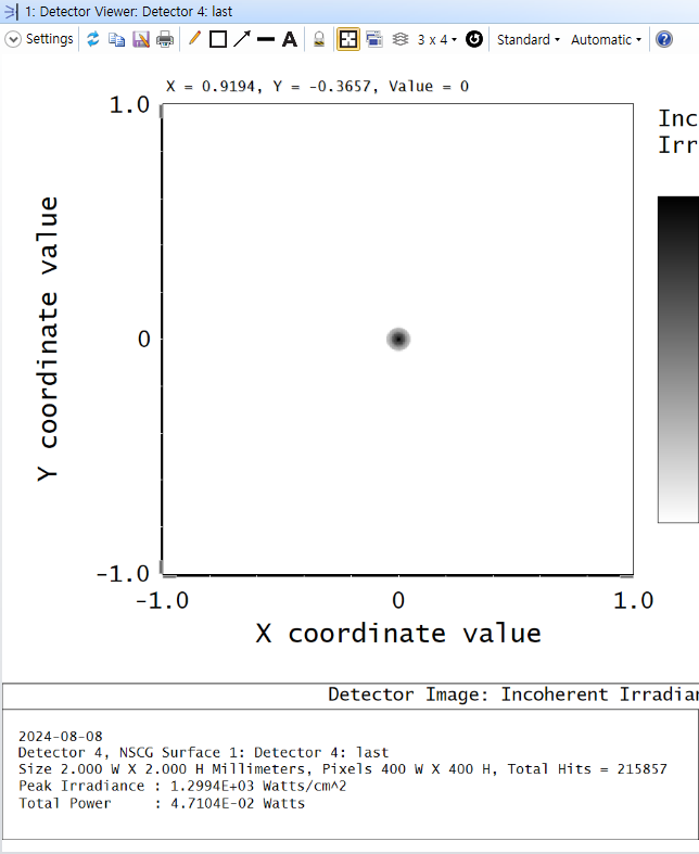
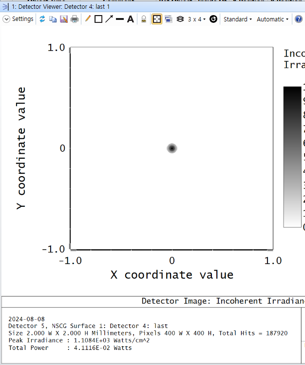
I want to optimize 'Total Power' of last detector(the right end of fiber) to get maximum value. Total power at source is 1W.
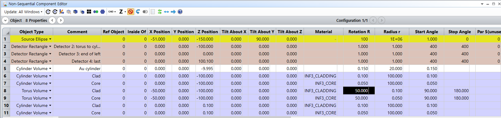
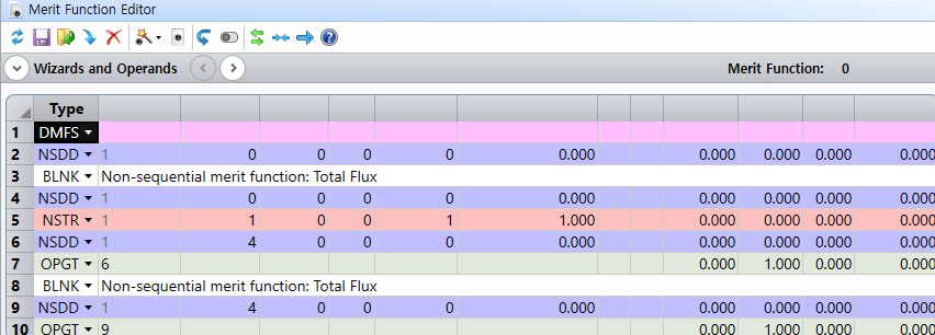
In my NSC Editor, there are 3 truncated fiber (6-7 object: middle section of fiber, 8-9 object: curved section of fiber, 10-11 object: right section of fiber)
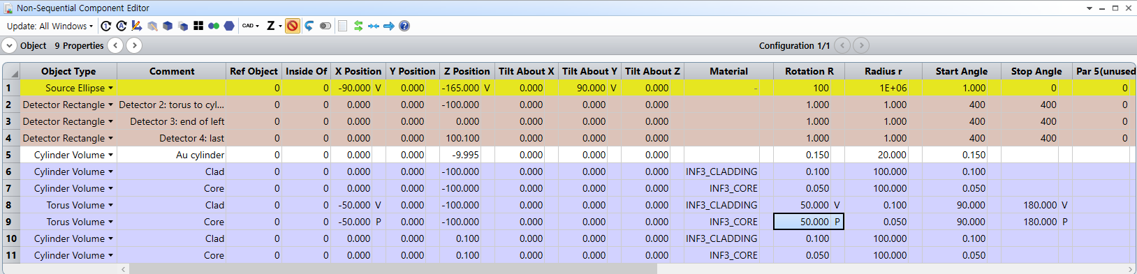
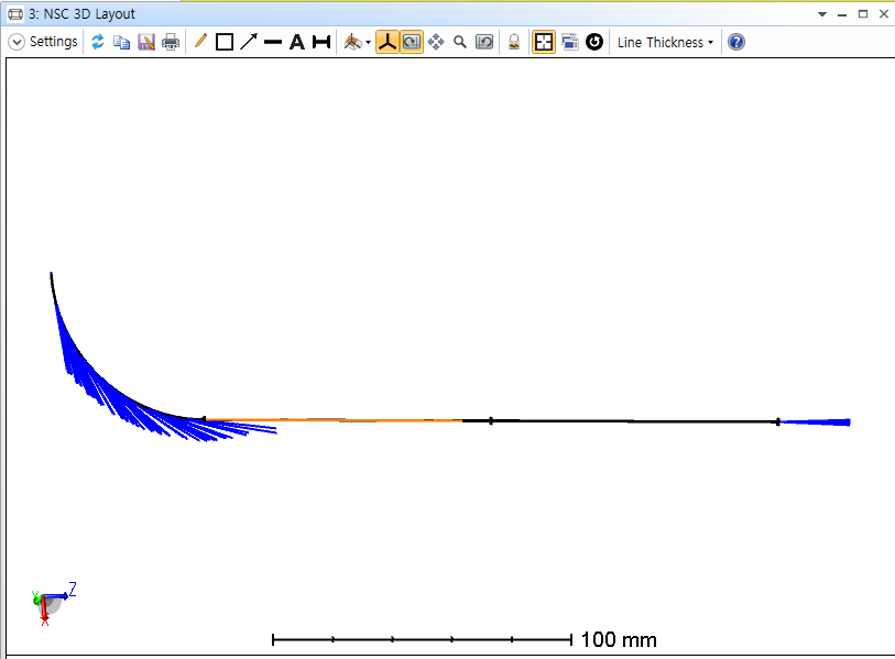
1 Au Cylinder which covers around a slight gap between middle section and right section of fiber. The gap is 0.1 mm. (this would be mentioned at question 2.)
Variables that I think should be optimized are as follows :
<Source Ellipse>: X position, Z position, Tilt About Y - Y position must be fixed. All the simulation components have same values of Y. (similar to X-Z plane simulation)
<Torus Volume(Core)>: X position, Rotation R, Stop Angle - I want to optimize only curve section of fiber, not straight section.
<Torus Volume(Cladding)>: X position, Rotation R, Stop Angle - These are all pickup from same parameter of 'Torus Volume(Core)'
Consequently, there are 6 variables in total and optimization region would be only left section (curved section) of fiber.
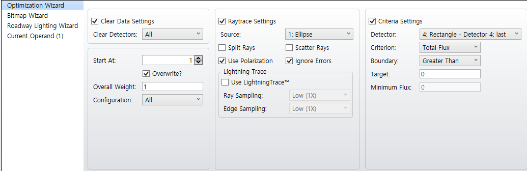
I attached my Optimization Wizard and Operands.
(If we scale up 'radius r' to the order of 100 compared to 'Rotation R', It runs well without any power loss - efficiency is almost over 70%. However, It does not make sense because an actual fiber has very small radius. So, now I fix 'Front R' and 'Back R' of Cylinder Volume and only impose variation on Torus Volume.)
My questions are as follows :
1. I usually do my optimization by Hammer Current. In attached photos below, my merit function does not arise from 0.00 during enough running time. I think I have to set 'Target' in <Optimization Wizard - Criteria Settings - Target>. However, flux has different unit, lumen, and Total Power's unit in detector viewer is Watts. I know 'luminous flux = power(W) x luminous efficacy(lm/W)'.
Then, what is luminous efficacy of Source Ellipse in Zemax ? I would put my own flux criterion by calculating the above expression (luminous flux).
If there are any other suggestions for optimization operands, all recommendations are welcome.
2. I displace a Cylinder Volume(the object #5) on slight air gap region(0.1 mm), and also try to set material of this object as Au. However, I cannot find the way to add absorption coefficient of material. Is it possible to set absorptive material in Zemax? (I already know how to use coating in absolute thickness. But I wonder if the cylinder is coated in radial direction, inside or outside)
cf)
add material INF3_CORE, INF3_CLADDING (material catalog -> index data from Thorlab)
Index information comes from Thorlab - multimode fiber (INF3)
We design a fiber which is composed of CORE (refractive index: 1.489) and CLADDING (refractive index: 1.476) at source wavelength 3.3um.
I look forward to your reply.
Thank you.