Solved

Shear interferometer

  • 14 April 2023
  • 7 replies
  • 521 views

Hi everyone.


No so long time ago I purchased the Shear plate (interferometer) from Newport https://www.newport.com/f/shear-plate-collimation-tester. The goal is to used it to evaluate the divergence of a beam expander (depending on the orientation of the interference fringes you can judge whether the beam expander is collimated, converging, or diverging).


The beam expander that I want to evaluate is Galilean (custom designed). 


From the real measurements it is not always clear the orientation of the fringes and the number of fringes and there quality is quite poor, so I would like to simulate (or to get the Interferogram) in Zemax to correlate the real measurements with simulations.

I guess, I neeed to use the Interferogram or wavefront map for it, however I am not very experienced with them. 


So, from the simulations I would like to get the interferogram that will be changing the orientation of the fringes by changing the distance between the lenses in beam expander. 


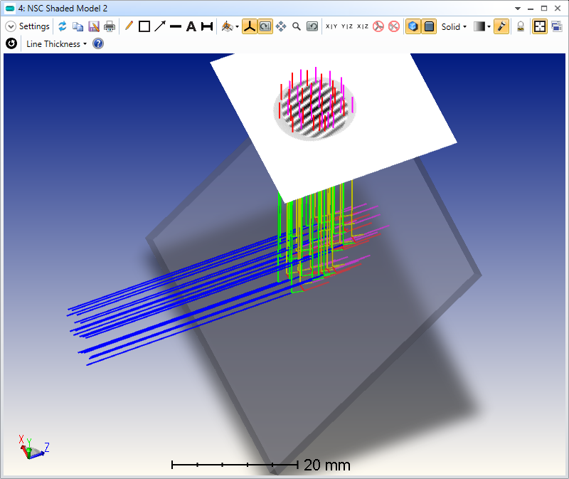
See the image down below.


Thank you in advance!


Best,

Alina

icon

Best answer by Mark.Nicholson 14 April 2023, 18:36

View original

7 replies

Userlevel 7
Badge +3

Hi Alina,

You can use Non-sequential mode to model a shear plate. I’ve attached a quick sample file. The reflections from the front and rear surfaces of a slightly wedged window:

are combined coherently to show shear fringes:

  • Mark
Userlevel 7
Badge +3

P.S. It looks really cool on the Shaded model:


Badge

Hi,


This is very helpful, Mark.  

I also would like to model a system which I am analyzing with a shearing interferometer.  My design includes a black box of a Powell lens, plus a number of other lenses.  I would like to introduce decenters, tilts, etc. to the design to determine likely error sources in the fringe pattern I am getting, which is not as good as I expect.  I don’t know if the errors are due to defects in the lenses, the lens positions, or a combination.  

It seems like I have a couple of options, neither of them ideal:

  1. I can make a sequential model of the Powell lens and convert the entire lens to non-sequential.  There is a risk my model of the Powell lens won’t be accurate.
  2. I can leave the model sequential and try to simulate the shear plate in this mode.  I have more confidence in the lens design model but don’t know if it is possible to model the shear plate in sequential mode.

Is there a better solution which I am not aware of?  

Thanks

David Aziz


Userlevel 7
Badge +3

I’d use option 1: built the model in sequential and then convert it to non-sequential. You should achieve 100% accuracy of the ray tracing results in seq and ns. I don’t really see what’s ‘non-ideal’ about this

There’s no way to model shear interferometry in sequential mode. It is inherently a non-seq process.

Userlevel 7
Badge +3

I looked at Powell Lenses in the Thorlab website and saw this:

I would make this model using a Polygon object, in either pure sequential or hybrid nonseq if you really need a sequential analysis that’s not available directly in sequential mode.

One caveat: don’t align it so that the gut ray hits exactly on the edge of the prism faces (i.e. right along the roof of the prism). There’s no meaningful derivative at an infinitely sharp edge. There’s no problem ‘in real life’ of course as no light would refract at such an edge for the same reason.  

Badge

Thanks, Mark.

I think the Powell lenses have a smooth curve, rather than sharp as implied by the Thorlabs drawing, which appears to be simplified.

What type of surface do you recommend using to model this?

Best regards

David


Userlevel 7
Badge +3

This link may be of some help: 

Regards,

Jeff

Reply