Hi John,
You can use the Zernike Standard Phase surface to introduce aberrations you want:
The Setup Tab > Editors Group (Setup Tab) > Lens Data Editor > Sequential Surfaces (lens data editor) > Zernike Standard Phase
You will find the description of the Zernike Standard Coefficients here:
The Analyze Tab (sequential ui mode) > Image Quality Group > Wavefront > Zernike Standard Coefficients
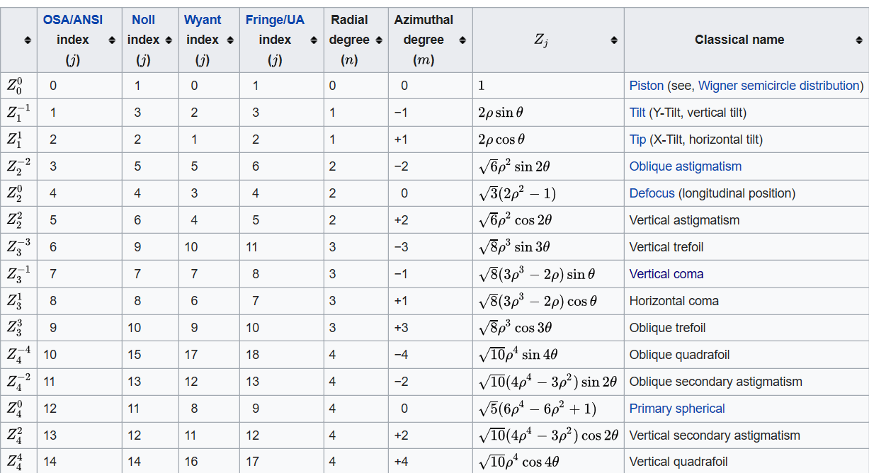
This table from Wikipedia (https://en.wikipedia.org/wiki/Zernike_polynomials) shows the relation between the equations and the corresponding aberration:
Here is another reference you may be interested in, as it relates the distortion with terms Z1 and Z2:
https://telescope-optics.net/zernike_coefficients.htm
However, both analysis (Zernike and Seidel) are calculated in a different way. Seidel coefficients are computed using paraxial ray trace data on a surface by surface basis, whereas Zernike coefficients are computed by tracing a grid of rays through the system which are integrated to get the wavefront at the exit pupil. This wave front is then fitted with the Zernike terms up to a specified order of terms.I’ve made a quick search on Google and it seems that there are some references if you want to convert from Zernike to Seidel, such as:
https://www.osapublishing.org/ol/abstract.cfm?uri=ol-7-6-262
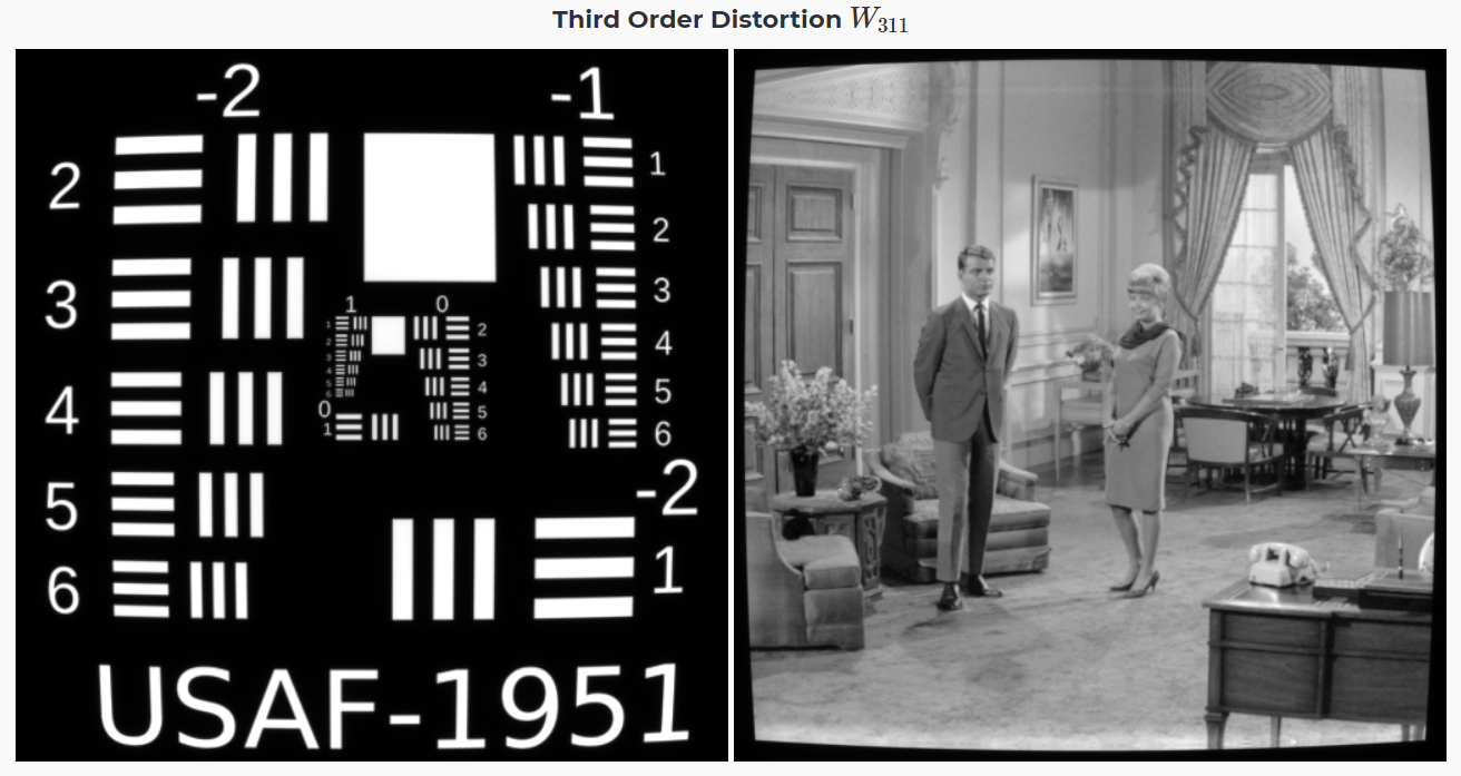
Some Seidel aberrations (such as spherical, astigmatism or coma) can be modelled directly with the Irregular Surface, but distortion is a tough one as it can not be easily described with this kind of surface. Since distortion is just the variation of focal length vs. field, you can try to design a wide angle lens. You may have a look at the example \Zemax\Samples\Sequential\Objectives\Wide angle lens 100 degree field.zmx where distortion can be seen with Image Simulation tool in a similar way of your example.
Best,
Berta